
ESP32-Based Password-Protected Relay Control with 4x4 Keypad
View and Edit Project In Cirkit Designer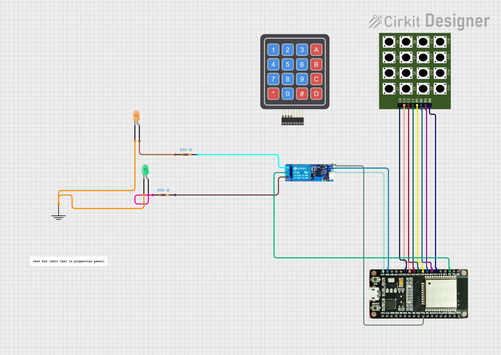
Circuit Documentation
Summary
This circuit is designed to control a relay module using an ESP32 microcontroller and a 4x4 keypad. The user can enter an 8-digit password via the keypad, and if the password is correct, the relay will activate, unlocking a connected device. The circuit also includes two LEDs (orange and green) to indicate the status of the relay.
Component List
ESP32-36PINS-DEVKIT-V1
- Description: A development board based on the ESP32 microcontroller.
- Pins: EN, IO36, IO39, IO34, IO35, IO32, IO33, IO25, IO26, IO27, IO14, IO12, IO13, IO09, IO10, IO11, GND, VIN, 3V3, IO06, IO07, IO08, IO00, IO15, IO02, IO04, IO16, IO17, IO05, IO18, IO19, IO21, IO03, IO01, IO22, IO23
4x4 Keypad
- Description: A 4x4 matrix keypad used for user input.
- Pins: C3, C2, C4, C1, R1, R2, R3, R4
Relay module 5v-30v
- Description: A relay module that can be triggered by a microcontroller to switch higher voltage loads.
- Pins: common contact, normally open, normally closed, trigger, V-, V+
LED: Two Pin (orange)
- Description: An orange LED used to indicate the status of the relay.
- Pins: cathode, anode
LED: Two Pin (green)
- Description: A green LED used to indicate the status of the relay.
- Pins: cathode, anode
Resistor (200 Ohms)
- Description: A resistor with a resistance of 200 Ohms.
- Pins: pin1, pin2
GND
- Description: Ground connection.
Wiring Details
ESP32-36PINS-DEVKIT-V1
- IO39 connected to Relay module 5v-30v (common contact)
- IO32 connected to 4x4 Keypad (R4)
- IO33 connected to 4x4 Keypad (R3)
- IO25 connected to 4x4 Keypad (R2)
- IO26 connected to 4x4 Keypad (R1)
- IO27 connected to 4x4 Keypad (C1)
- IO14 connected to 4x4 Keypad (C2)
- IO12 connected to 4x4 Keypad (C3)
- IO13 connected to 4x4 Keypad (C4)
- GND connected to Relay module 5v-30v (V-)
- VIN connected to Relay module 5v-30v (V+)
- IO17 connected to Relay module 5v-30v (trigger)
4x4 Keypad
- R4 connected to ESP32-36PINS-DEVKIT-V1 (IO32)
- R3 connected to ESP32-36PINS-DEVKIT-V1 (IO33)
- R2 connected to ESP32-36PINS-DEVKIT-V1 (IO25)
- R1 connected to ESP32-36PINS-DEVKIT-V1 (IO26)
- C1 connected to ESP32-36PINS-DEVKIT-V1 (IO27)
- C2 connected to ESP32-36PINS-DEVKIT-V1 (IO14)
- C3 connected to ESP32-36PINS-DEVKIT-V1 (IO12)
- C4 connected to ESP32-36PINS-DEVKIT-V1 (IO13)
Relay module 5v-30v
- common contact connected to ESP32-36PINS-DEVKIT-V1 (IO39)
- V- connected to ESP32-36PINS-DEVKIT-V1 (GND)
- V+ connected to ESP32-36PINS-DEVKIT-V1 (VIN)
- trigger connected to ESP32-36PINS-DEVKIT-V1 (IO17)
- normally open connected to Resistor (pin2)
- normally closed connected to Resistor (pin2)
LED: Two Pin (orange)
- cathode connected to GND
- anode connected to Resistor (pin1)
LED: Two Pin (green)
- cathode connected to GND
- anode connected to Resistor (pin1)
Resistor (200 Ohms)
- pin2 connected to Relay module 5v-30v (normally open)
- pin2 connected to Relay module 5v-30v (normally closed)
- pin1 connected to LED: Two Pin (orange) (anode)
- pin1 connected to LED: Two Pin (green) (anode)
Code Documentation
#define RELAY_PIN 17  // GPIO Pin connected to IN (trigger for relay)

// Define the password (8-digit password)
const char correctPassword[] = "12345678";  // Set your password here

// Variables for entering password
char enteredPassword[9];  // 8 digits + null terminator
int enteredIndex = 0;

// Pin mappings for the keypad (out1 - D32, out2 - D33, out3 - D25, out4 - D26, out5 - D27, out6 - D14, out7 - D12, out8 - D13)
const int keyPins[] = {32, 33, 25, 26, 27, 14, 12, 13};  // Declare the keyPins array

void setup() {
  Serial.begin(115200);

  // Initialize the relay pin
  pinMode(RELAY_PIN, OUTPUT);

  // Initialize the key pins
  for (int i = 0; i < 8; i++) {
    pinMode(keyPins[i], INPUT);
  }

  // Start with the relay off (NC is active by default)
  digitalWrite(RELAY_PIN, LOW);

  Serial.println("System initialized. Please enter the password.");
}

void loop() {
  // Read keys and detect which key is pressed
  for (int i = 0; i < 8; i++) {
    if (digitalRead(keyPins[i]) == HIGH) {  // Check if the key at the ith position is pressed
      char keyPressed = '1' + i;  // Map the pin index to the corresponding key (1-8)

      // Print the detected key
      Serial.print("Key pressed: ");
      Serial.println(keyPressed);

      // Store the pressed key
      if (enteredIndex < 8) {
        enteredPassword[enteredIndex] = keyPressed;
        enteredIndex++;
        enteredPassword[enteredIndex] = '\0';  // Null-terminate the string

        Serial.print("Entered: ");
        Serial.println(enteredPassword);
      }

      delay(200);  // Small delay to debounce keypress
    }
  }

  // If 8 digits are entered, check the password
  if (enteredIndex == 8) {
    if (checkPassword()) {
      Serial.println("Password is correct! Activating NO and unlocking...");

      // Unlock the lock (relay ON, NO is active)
      digitalWrite(RELAY_PIN, HIGH);

      delay(5000);  // Keep the lock open for 5 seconds

      // Turn off the relay after unlocking
      digitalWrite(RELAY_PIN, LOW);
      Serial.println("System relocked (no output).");
    } else {
      Serial.println("Incorrect password. NC remains active.");

      // Ensure relay stays in its default state (NC active)
      digitalWrite(RELAY_PIN, LOW);
    }

    // Reset the entered password for the next attempt
    resetPassword();
  }

  delay(100);  // Small delay to avoid flooding the serial monitor
}

// Function to check if entered password matches the correct password
bool checkPassword() {
  return (strcmp(enteredPassword, correctPassword) == 0);
}

// Reset the entered password
void resetPassword() {
  enteredIndex = 0;
  memset(enteredPassword, 0, sizeof(enteredPassword));
  Serial.println("Password reset. Please enter again.");
}
This code initializes the ESP32, sets up the relay and keypad pins, and continuously checks for key presses. When an 8-digit password is entered, it checks if the password is correct. If correct, it activates the relay to unlock a connected device for 5 seconds. If incorrect, it keeps the relay in its default state.