Cirkit Designer
Your all-in-one circuit design IDE
Home /
Project Documentation
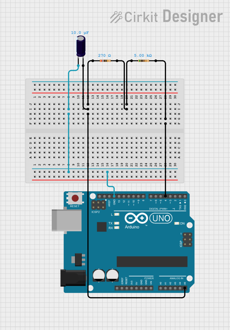
Arduino UNO-Based Sensor Interface with Capacitor and Resistor Network
Circuit Documentation
Summary
This document provides a detailed overview of a circuit consisting of resistors, an electrolytic capacitor, and an Arduino UNO microcontroller. The circuit is designed to interface with the Arduino UNO, utilizing its analog and digital pins for various functionalities.
Component List
Resistor
- Description: A passive electrical component that implements electrical resistance as a circuit element.
- Pins: pin1, pin2
- Properties:
- Resistance: 5000 Ohms
Resistor
- Description: A passive electrical component that implements electrical resistance as a circuit element.
- Pins: pin1, pin2
- Properties:
- Resistance: 270 Ohms
Electrolytic Capacitor
- Description: A type of capacitor that uses an electrolyte to achieve a larger capacitance than other capacitor types.
- Pins: -, +
- Properties:
- Capacitance: 0.00001 Farads
Arduino UNO
- Description: A microcontroller board based on the ATmega328P. It has 14 digital input/output pins, 6 analog inputs, a 16 MHz quartz crystal, a USB connection, a power jack, an ICSP header, and a reset button.
- Pins: UNUSED, IOREF, Reset, 3.3V, 5V, GND, Vin, A0, A1, A2, A3, A4, A5, SCL, SDA, AREF, D13, D12, D11, D10, D9, D8, D7, D6, D5, D4, D3, D2, D1, D0
Wiring Details
Resistor (5000 Ohms)
- pin1 is connected to pin2 of the 270 Ohms resistor.
- pin2 is connected to D4 of the Arduino UNO.
Resistor (270 Ohms)
- pin1 is connected to pin1 of the 5000 Ohms resistor and A5 of the Arduino UNO.
- pin2 is connected to pin1 of the 5000 Ohms resistor.
Electrolytic Capacitor
- - is connected to GND of the Arduino UNO.
- + is connected to pin1 of the 270 Ohms resistor and A5 of the Arduino UNO.
Arduino UNO
- GND is connected to - of the electrolytic capacitor.
- A5 is connected to + of the electrolytic capacitor and pin1 of the 270 Ohms resistor.
- D4 is connected to pin2 of the 5000 Ohms resistor.
Documented Code
Arduino UNO Code
void setup() {
  // put your setup code here, to run once:

}

void loop() {
  // put your main code here, to run repeatedly:

}
This code is a basic template for the Arduino UNO, containing empty setup and loop functions. The setup function runs once when the microcontroller is powered on or reset, and the loop function runs continuously after the setup function has completed.