Cirkit Designer
Your all-in-one circuit design IDE
Home /
Project Documentation
Arduino UNO-Based Smart Temperature Control System with LCD Display and Relay Modules
Circuit Documentation
Summary
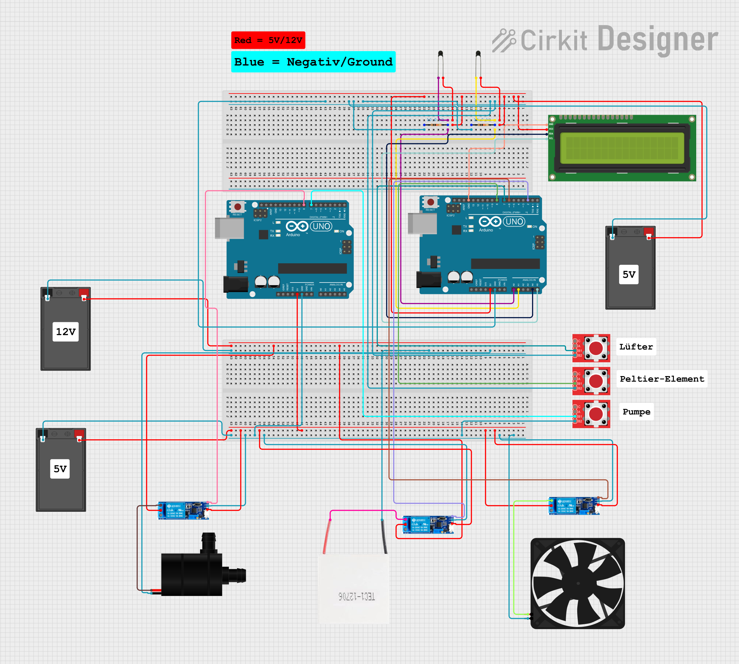
This circuit involves multiple components including resistors, NTC thermistors, an I2C LCD screen, an Arduino UNO, a battery, LED tactile button breakouts, relay modules, a Peltier module, a water pump, and a fan. The circuit is designed to interface with sensors and actuators, controlled by two Arduino UNO microcontrollers. The circuit also includes an I2C LCD screen for display purposes.
Component List
Resistor
- Description: A passive electrical component with a resistance of 10k Ohms.
- Pins: pin1, pin2
Arduino UNO
- Description: A microcontroller board based on the ATmega328P.
- Pins: UNUSED, IOREF, Reset, 3.3V, 5V, GND, Vin, A0, A1, A2, A3, A4, A5, SCL, SDA, AREF, D13, D12, D11, D10, D9, D8, D7, D6, D5, D4, D3, D2, D1, D0
NTC Thermistor
- Description: A type of resistor whose resistance varies significantly with temperature.
- Pins: A0, A1
I2C LCD 16x2 Screen
- Description: A 16x2 character LCD screen with I2C interface.
- Pins: SCL, SDA, VCC (5V), GND, VDD, VO, RS, RW, E, D0, D1, D2, D3, D4, D5, D6, D7, BLA, BLK
Battery
- Description: A power source for the circuit.
- Pins: -, +
LED Tactile Button Breakout
- Description: A breakout board for an LED tactile button.
- Pins: C, B1, B2, A
Relay Module 5V-30V
- Description: A relay module that can be triggered by a 5V-30V signal.
- Pins: common contact, normally open, normally closed, trigger, V-, V+
Peltier Module
- Description: A thermoelectric cooler.
- Pins: Negative, Positive
Water Pump
- Description: A small water pump.
- Pins: VCC, GND
Fan
- Description: A small fan.
- Pins: GND, 5V
Wiring Details
Resistor
Resistor 1
- pin1: Connected to pin1 of another resistor, B2 of two LED tactile button breakouts, - of the battery, and GND of the Arduino UNO.
- pin2: Connected to A1 of the Arduino UNO and A0 of an NTC thermistor.
Resistor 2
- pin1: Connected to pin1 of another resistor, B2 of two LED tactile button breakouts, - of the battery, and GND of the Arduino UNO.
- pin2: Connected to A0 of the Arduino UNO and A0 of another NTC thermistor.
Arduino UNO
Arduino UNO 1
- 5V: Connected to VCC (5V) of the I2C LCD screen, + of the battery, and A1 of two NTC thermistors.
- GND: Connected to pin1 of two resistors, B2 of two LED tactile button breakouts, and - of the battery.
- A1: Connected to pin2 of a resistor and A0 of an NTC thermistor.
- A0: Connected to pin2 of another resistor and A0 of another NTC thermistor.
- A4: Connected to SDA of the I2C LCD screen.
- A5: Connected to SCL of the I2C LCD screen.
- D8: Connected to B1 of an LED tactile button breakout.
- D7: Connected to B1 of another LED tactile button breakout.
- D6: Connected to the trigger of a relay module.
- D2: Connected to the trigger of another relay module.
Arduino UNO 2
- 5V: Connected to V+ and common contact of three relay modules, and + of another battery.
- GND: Connected to V- of three relay modules, B2 of an LED tactile button breakout, and - of another battery.
- D8: Connected to the trigger of a relay module.
- D7: Connected to B1 of an LED tactile button breakout.
NTC Thermistor
NTC Thermistor 1
- A0: Connected to pin2 of a resistor and A0 of the Arduino UNO.
- A1: Connected to A1 of another NTC thermistor, VCC (5V) of the I2C LCD screen, + of the battery, and 5V of the Arduino UNO.
NTC Thermistor 2
- A0: Connected to pin2 of another resistor and A0 of the Arduino UNO.
- A1: Connected to A1 of another NTC thermistor, VCC (5V) of the I2C LCD screen, + of the battery, and 5V of the Arduino UNO.
I2C LCD 16x2 Screen
- SCL: Connected to A5 of the Arduino UNO.
- SDA: Connected to A4 of the Arduino UNO.
- VCC (5V): Connected to A1 of two NTC thermistors, + of the battery, and 5V of the Arduino UNO.
- GND: Connected to GND of the Arduino UNO.
Battery
Battery 1
- +: Connected to VCC (5V) of the I2C LCD screen, A1 of two NTC thermistors, and 5V of the Arduino UNO.
- -: Connected to pin1 of two resistors, B2 of two LED tactile button breakouts, and GND of the Arduino UNO.
Battery 2
- +: Connected to V+ and common contact of three relay modules, and 5V of the Arduino UNO.
- -: Connected to V- of three relay modules, B2 of an LED tactile button breakout, and GND of the Arduino UNO.
LED Tactile Button Breakout
LED Tactile Button Breakout 1
- B1: Connected to D8 of the Arduino UNO.
- B2: Connected to pin1 of two resistors, - of the battery, and GND of the Arduino UNO.
LED Tactile Button Breakout 2
- B1: Connected to D7 of the Arduino UNO.
- B2: Connected to pin1 of two resistors, - of the battery, and GND of the Arduino UNO.
LED Tactile Button Breakout 3
- B1: Connected to D7 of another Arduino UNO.
- B2: Connected to V- of three relay modules, - of another battery, and GND of another Arduino UNO.
Relay Module 5V-30V
Relay Module 1
- V+: Connected to 5V of another Arduino UNO and + of another battery.
- V-: Connected to GND of another Arduino UNO, B2 of an LED tactile button breakout, and - of another battery.
- trigger: Connected to D6 of the Arduino UNO.
- common contact: Connected to V+ of another Arduino UNO and + of another battery.
- normally open: Connected to 5V of the fan.
Relay Module 2
- V+: Connected to 5V of another Arduino UNO and + of another battery.
- V-: Connected to GND of another Arduino UNO, B2 of an LED tactile button breakout, and - of another battery.
- trigger: Connected to D2 of the Arduino UNO.
- common contact: Connected to + of another battery.
- normally open: Connected to Positive of the Peltier module.
Relay Module 3
- V+: Connected to 5V of another Arduino UNO and + of another battery.
- V-: Connected to GND of another Arduino UNO, B2 of an LED tactile button breakout, and - of another battery.
- trigger: Connected to D8 of another Arduino UNO.
- common contact: Connected to + of another battery.
- normally open: Connected to VCC of the water pump.
Peltier Module
- Negative: Connected to GND of the water pump and - of another battery.
- Positive: Connected to normally open of a relay module.
Water Pump
- GND: Connected to Negative of the Peltier module and - of another battery.
- VCC: Connected to normally open of a relay module.
Fan
- GND: Connected to V- of three relay modules, B2 of an LED tactile button breakout, and - of another battery.
- 5V: Connected to normally open of a relay module.
Documented Code
Arduino UNO 1
void setup() {
  // put your setup code here, to run once:

}

void loop() {
  // put your main code here,