Cirkit Designer
Your all-in-one circuit design IDE
Home /
Project Documentation
Arduino Nano Controlled Fingerprint-Activated Solenoid Lock
Circuit Documentation
Summary of the Circuit
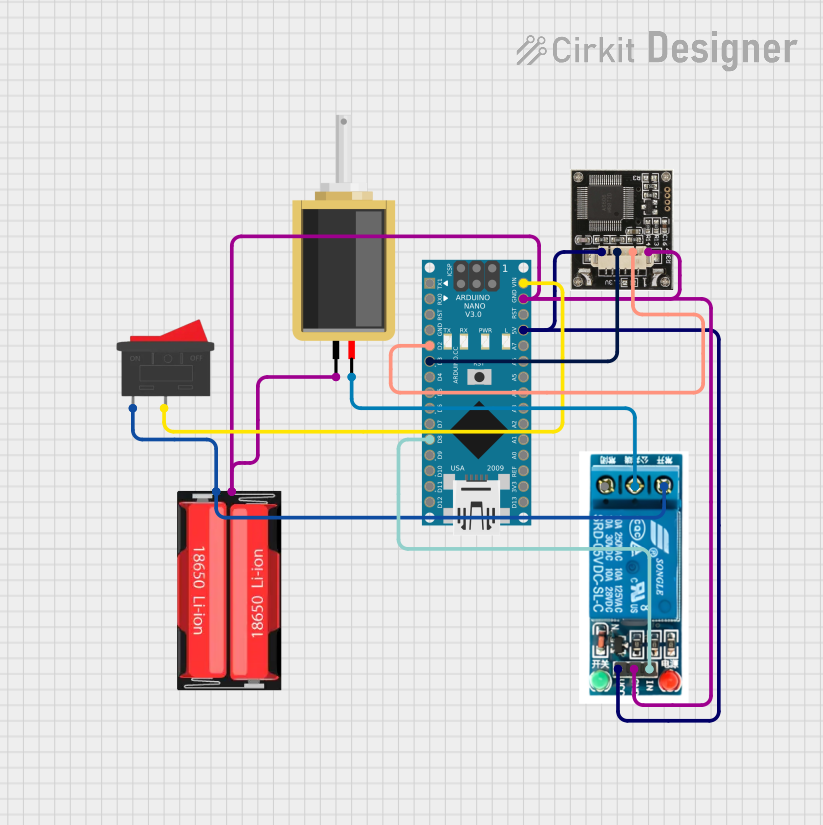
This circuit is designed to interface an Arduino Nano with an R307 fingerprint sensor module, control a solenoid lock through a 5V relay, and manage power through a rocker switch and an 18650 Li-Ion battery. The Arduino Nano serves as the central processing unit, receiving data from the R307 fingerprint sensor and controlling the solenoid lock via the relay based on the fingerprint authentication. The rocker switch is used to control the power flow from the battery to the circuit, ensuring an on/off capability.
Component List
Arduino Nano
- Microcontroller board based on the ATmega328P
- It has a variety of digital and analog I/O pins for interfacing with various components.
R307 Fingerprint Sensor
- A fingerprint scanner module capable of storing and comparing fingerprints for authentication purposes.
Solenoid Lock
- An electromagnetic lock that can be actuated to lock or unlock a mechanism.
Rocker Switch
- A simple on/off switch to control the power supply to the circuit.
18650 Li-Ion Battery
- A rechargeable battery providing the power source for the circuit.
5V Relay
- An electromechanical switch that allows the Arduino to control higher power devices, like the solenoid lock.
Wiring Details
Arduino Nano
D2connected toTXof R307 Fingerprint SensorD3connected toRXof R307 Fingerprint SensorD8connected toInof 5V RelayVINconnected to2of Rocker SwitchGNDconnected to common ground net5Vconnected toVCCof R307 Fingerprint Sensor andVCCof 5V Relay
R307 Fingerprint Sensor
TXconnected toD2of Arduino NanoRXconnected toD3of Arduino NanoGNDconnected to common ground netVCCconnected to5Vof Arduino Nano
Solenoid Lock
pin1connected to common ground netpin2connected toCommon terminalof 5V Relay
Rocker Switch
1connected toPositiveof 18650 Li-Ion Battery andNormally Openof 5V Relay2connected toVINof Arduino Nano
18650 Li-Ion Battery
Positiveconnected to1of Rocker Switch andNormally Openof 5V RelayNegativeconnected to common ground net
5V Relay
Normally Openconnected to1of Rocker Switch andPositiveof 18650 Li-Ion BatteryCommon terminalconnected topin2of Solenoid LockInconnected toD8of Arduino NanoGNDconnected to common ground netVCCconnected to5Vof Arduino Nano
Documented Code
Arduino Nano Code (sketch.ino)
void setup() {
  // put your setup code here, to run once:

}

void loop() {
  // put your main code here, to run repeatedly:

}
Note: The provided code is a template and does not contain any functional code to operate the circuit. The user must implement the setup and loop functions to initialize the components and define the circuit's behavior.