
NPN Transistor-Based Voltage Measurement Circuit with Dual Power Supplies
View and Edit Project In Cirkit Designer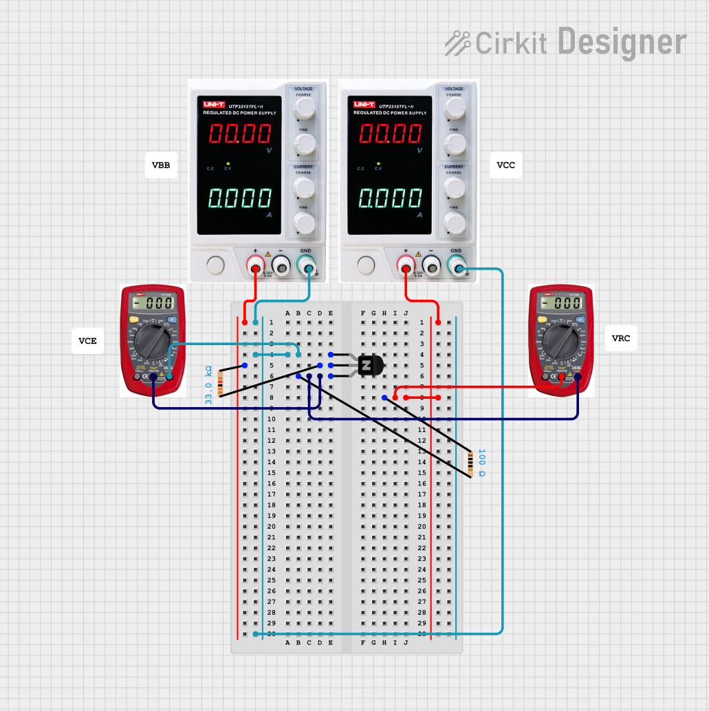
Circuit Documentation
Summary
This document provides a detailed overview of a circuit consisting of an NPN transistor, power supplies, resistors, and multimeters. The circuit is designed to demonstrate the basic operation of an NPN transistor in conjunction with resistors and power supplies, with measurements taken using multimeters.
Component List
NPN Transistor (CBE)
- Pins: collector, base, emitter
- Description: A standard NPN transistor used for switching and amplification.
Power Supply
- Pins: +, -, GND
- Description: Provides the necessary voltage and current for the circuit.
Resistor (33k Ohms)
- Pins: pin1, pin2
- Description: A resistor with a resistance of 33k Ohms.
Resistor (100 Ohms)
- Pins: pin1, pin2
- Description: A resistor with a resistance of 100 Ohms.
Multimeter
- Pins: COM, V, A
- Description: Used to measure voltage, current, and resistance in the circuit.
Wiring Details
NPN Transistor (CBE)
Collector:
- Connected to GND of Power Supply 1
- Connected to GND of Power Supply 2
- Connected to COM of Multimeter 2
Base:
- Connected to pin1 of Resistor (33k Ohms)
Emitter:
- Connected to pin2 of Resistor (100 Ohms)
- Connected to COM of Multimeter 1
- Connected to V of Multimeter 2
Power Supply 1
+:
- Connected to pin2 of Resistor (33k Ohms)
GND:
- Connected to collector of NPN Transistor
- Connected to COM of Multimeter 2
- Connected to GND of Power Supply 2
Power Supply 2
+:
- Connected to pin1 of Resistor (100 Ohms)
- Connected to V of Multimeter 1
GND:
- Connected to collector of NPN Transistor
- Connected to COM of Multimeter 2
- Connected to GND of Power Supply 1
Resistor (33k Ohms)
pin1:
- Connected to base of NPN Transistor
pin2:
- Connected to + of Power Supply 1
Resistor (100 Ohms)
pin1:
- Connected to + of Power Supply 2
pin2:
- Connected to emitter of NPN Transistor
- Connected to COM of Multimeter 1
- Connected to V of Multimeter 2
Multimeter 1
COM:
- Connected to emitter of NPN Transistor
- Connected to pin2 of Resistor (100 Ohms)
V:
- Connected to + of Power Supply 2
Multimeter 2
COM:
- Connected to collector of NPN Transistor
- Connected to GND of Power Supply 1
- Connected to GND of Power Supply 2
V:
- Connected to emitter of NPN Transistor
- Connected to pin2 of Resistor (100 Ohms)
Code
There is no embedded code associated with this circuit.