
ESP32-Based Audio Frequency Analyzer with I2C LCD Display and Pushbutton Control
View and Edit Project In Cirkit Designer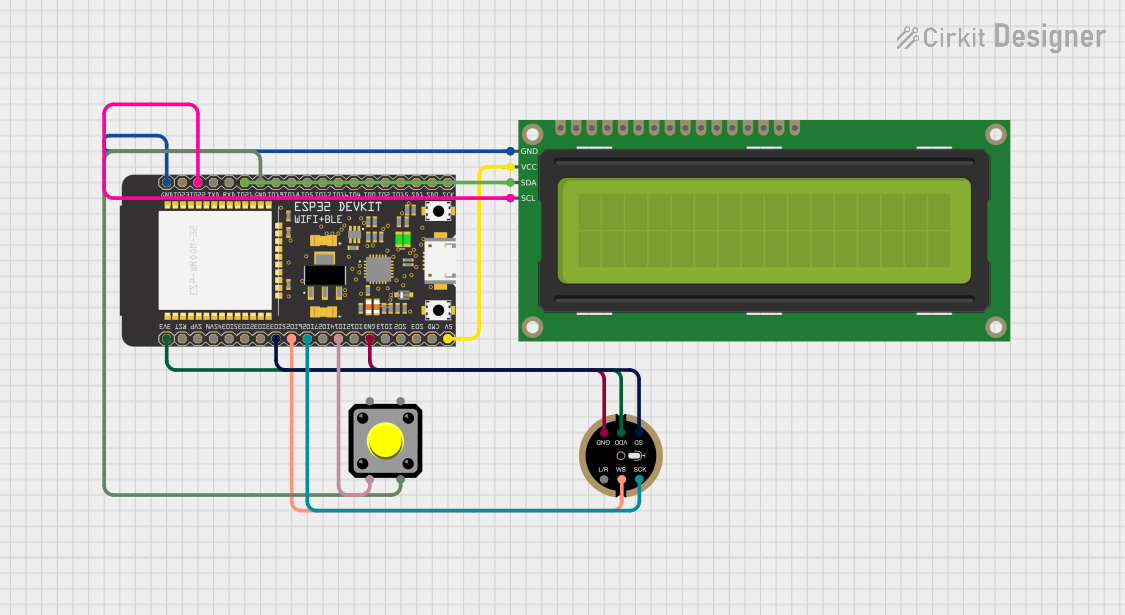
Circuit Documentation
Summary
This document provides a detailed overview of a circuit that includes an ESP32 microcontroller, an INMP441 microphone, a 16x2 I2C LCD, and a pushbutton. The circuit is designed to record audio, perform FFT analysis, and display the highest frequency detected on the LCD. The pushbutton is used to start and stop the recording process.
Component List
INMP441 FRONT MIC
- Description: A high-performance, low-power, digital-output, omnidirectional MEMS microphone.
- Pins: L/R, WS, SCK, SD, VDD, GND
16x2 I2C LCD
- Description: A 16x2 character LCD display with I2C interface.
- Pins: GND, VCC, SDA, SCL
ESP32 Wroom
- Description: A powerful, generic Wi-Fi+BT+BLE MCU module that targets a wide variety of applications.
- Pins: 2 (3V3), 3 (Reset), 4 (GPIO36), 5 (GPIO39), 6 (GPIO34), 7 (GPIO35), 8 (GPIO32), 9 (GPIO33), 10 (GPIO25), 11 (GPIO26), 12 (GPIO27), 13 (GPIO14), 14 (GPIO12), GND, 16 (GPIO13), 17 (GPIO9), 18 (GPIO10), 19 (GPIO11), 5V, 37 (GPIO23), 36 (GPIO22/SCL), 35 (GPIO1/TXD0), 34 (GPIO3/RXD0), 33 (GPIO21/SDA), 31 (GPIO19), 30 (GPIO18), 29 (GPIO5), 28 (GPIO17), 27 (GPIO16), 26 (GPIO4), 25 (GPIO0), 24 (GPIO2), 23 (GPIO15), 22 (GPIO8), 21 (GPIO7), 20 (GPIO6)
Pushbutton
- Description: A simple pushbutton used for user input.
- Pins: Pin 2, Pin 1, Pin 3, Pin 4
Wiring Details
INMP441 FRONT MIC
- VDD connected to ESP32 Wroom pin 2 (3V3)
- SD connected to ESP32 Wroom pin 9 (GPIO33)
- WS connected to ESP32 Wroom pin 10 (GPIO25)
- SCK connected to ESP32 Wroom pin 11 (GPIO26)
- GND connected to ESP32 Wroom pin GND
16x2 I2C LCD
- VCC connected to ESP32 Wroom pin 5V
- GND connected to ESP32 Wroom pin GND
- SCL connected to ESP32 Wroom pin 36 (GPIO22/SCL)
- SDA connected to ESP32 Wroom pin 33 (GPIO21/SDA)
ESP32 Wroom
- 2 (3V3) connected to INMP441 FRONT MIC pin VDD
- 9 (GPIO33) connected to INMP441 FRONT MIC pin SD
- 10 (GPIO25) connected to INMP441 FRONT MIC pin WS
- 11 (GPIO26) connected to INMP441 FRONT MIC pin SCK
- 13 (GPIO14) connected to Pushbutton pin Pin 2
- GND connected to INMP441 FRONT MIC pin GND
- 5V connected to 16x2 I2C LCD pin VCC
- GND connected to 16x2 I2C LCD pin GND
- 36 (GPIO22/SCL) connected to 16x2 I2C LCD pin SCL
- 33 (GPIO21/SDA) connected to 16x2 I2C LCD pin SDA
- GND connected to Pushbutton pin Pin 3
Pushbutton
- Pin 2 connected to ESP32 Wroom pin 13 (GPIO14)
- Pin 3 connected to ESP32 Wroom pin GND
Code Documentation
#include <arduinoFFT.h>
#include <Wire.h>
#include <LiquidCrystal_I2C.h>
#include <driver/i2s.h>

// Pin configuration for I2S
#define I2S_BCK_PIN 26  // Bit Clock (SCK)
#define I2S_WS_PIN 25   // Word Select (WS)
#define I2S_DOUT_PIN 33 // Data Output (SO)

// Button configuration
#define BUTTON_PIN 14    // GPIO pin for button
#define DEBOUNCE_DELAY 50 // Debounce delay in milliseconds

// LCD configuration
LiquidCrystal_I2C lcd(0x27, 16, 2);

// FFT configuration
#define SAMPLES 1024
#define SAMPLING_FREQUENCY 16000

float vReal[SAMPLES];
float vImag[SAMPLES];
ArduinoFFT<float> FFT = ArduinoFFT<float>(vReal, vImag, SAMPLES, SAMPLING_FREQUENCY);

int32_t samples[SAMPLES];
size_t bytes_read;
bool isRecording = false;
float highestFrequency = 0;
unsigned long lastButtonPressTime = 0;
bool buttonState = false; // Stores the last known state of the button

void setup() {
  lcd.init();
  lcd.backlight();
  lcd.print("Initializing...");
  delay(2000);
  lcd.clear();

  // Configure button pin with internal pull-up
  pinMode(BUTTON_PIN, INPUT_PULLUP);

  i2s_config_t i2s_config = {
    .mode = i2s_mode_t(I2S_MODE_MASTER | I2S_MODE_RX),
    .sample_rate = SAMPLING_FREQUENCY,
    .bits_per_sample = I2S_BITS_PER_SAMPLE_32BIT,
    .channel_format = I2S_CHANNEL_FMT_ONLY_LEFT,
    .communication_format = I2S_COMM_FORMAT_I2S,
    .intr_alloc_flags = ESP_INTR_FLAG_LEVEL1,
    .dma_buf_count = 8,
    .dma_buf_len = 64
  };

  i2s_pin_config_t pin_config = {
    .bck_io_num = I2S_BCK_PIN,
    .ws_io_num = I2S_WS_PIN,
    .data_out_num = -1,
    .data_in_num = I2S_DOUT_PIN
  };

  i2s_driver_install(I2S_NUM_0, &i2s_config, 0, NULL);
  i2s_set_pin(I2S_NUM_0, &pin_config);
}

void loop() {
  bool currentButtonState = digitalRead(BUTTON_PIN) == LOW;

  // Debounce logic
  if (currentButtonState && !buttonState && (millis() - lastButtonPressTime > DEBOUNCE_DELAY)) {
    buttonState = true;
    lastButtonPressTime = millis();

    if (!isRecording) {
      isRecording = true;
      highestFrequency = 0;
      unsigned long startTime = millis();
      lcd.clear();
      lcd.print("Recording...");

      while (millis() - startTime < 3000) {
        recordFrequency();
      }

      lcd.clear();
      lcd.setCursor(0, 0);
      lcd.print("Highest Freq:");
      lcd.setCursor(0, 1);
      lcd.print(highestFrequency, 2);
      lcd.print(" Hz");
    } else {
      isRecording = false;
      lcd.clear();
      lcd.print("Click to show");
      lcd.setCursor(0, 1);
      lcd.print("frequency");
    }
  }

  if (!currentButtonState) {
    buttonState = false;
  }
}

void recordFrequency() {
  i2s_read(I2S_NUM_0, samples, sizeof(samples), &bytes_read, portMAX_DELAY);

  // Convert samples to float values for FFT processing
  for (int i = 0; i < SAMPLES; i++) {
    vReal[i] = (float)(samples[i] >> 8);  // Shift the sample data to remove noise
    vImag[i] = 0;  // No imaginary component for real signals
  }

  // Apply windowing function and compute FFT
  FFT.windowing(vReal, SAMPLES, FFT_WIN_TYP_HAMMING, FFT_FORWARD);
  FFT.compute(vReal, vImag, SAMPLES, FFT_FORWARD);
  FFT.complexToMagnitude(vReal, vImag, SAMPLES);

  // Find the major peak in the FFT output
  float currentFrequency = FFT.majorPeak(vReal, SAMPLES, SAMPLING_FREQUENCY);

  // Update highest frequency if the current frequency is higher
  if (currentFrequency > highestFrequency) {
    highestFrequency = currentFrequency;
  }
}
This code initializes the LCD, configures the I2S interface for the microphone, and sets up the pushbutton with a debounce mechanism. The main loop checks the button state