
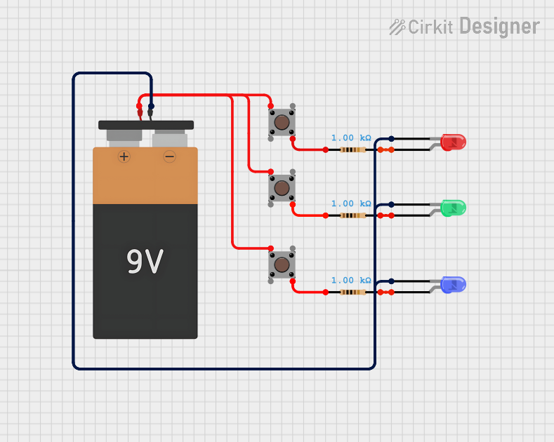
Circuit Documentation
Summary of the Circuit
This circuit consists of a series of LEDs, resistors, and pushbuttons powered by a 9V battery. Each LED is connected in series with a resistor and controlled by a pushbutton. The cathodes of all LEDs are connected together and to the ground (GND) of the battery, forming a common ground. The anodes of each LED are connected to a resistor, which in turn is connected to a pushbutton. The pushbuttons are used to control the flow of current to the LEDs, allowing them to be turned on and off independently. The battery provides the necessary voltage to power the circuit.
Component List
LEDs
- LED: Two Pin (red): A red light-emitting diode with two pins, anode and cathode.
- LED: Two Pin (green): A green light-emitting diode with two pins, anode and cathode.
- LED: Two Pin (blue): A blue light-emitting diode with two pins, anode and cathode.
Resistors
- Resistor: A component with a resistance of 1000 Ohms, used to limit the current through the LEDs.
Pushbuttons
- Pushbutton: A momentary switch with four pins, two for the input and two for the output.
Battery
- Battery 9V: A 9-volt battery with two pins, VCC and GND, used to provide power to the circuit.
Wiring Details
LED: Two Pin (red)
- Cathode: Connected to the common ground.
- Anode: Connected to a 1000 Ohm resistor.
LED: Two Pin (green)
- Cathode: Connected to the common ground.
- Anode: Connected to a 1000 Ohm resistor.
LED: Two Pin (blue)
- Cathode: Connected to the common ground.
- Anode: Connected to a 1000 Ohm resistor.
Resistor (1000 Ohms)
- Pin1: Connected to a pushbutton (Pin 4 out).
- Pin2: Connected to the anode of an LED.
Pushbutton
- Pin 1 (in): Connected to the VCC of the battery.
- Pin 2 (in): Not used in this circuit.
- Pin 3 (out): Not used in this circuit.
- Pin 4 (out): Connected to a resistor (Pin1).
Battery 9V
- VCC: Connected to the input pins (Pin 1 in) of all pushbuttons.
- GND: Connected to the cathodes of all LEDs, forming a common ground.
Documented Code
There is no microcontroller or embedded code associated with this circuit as per the provided inputs. Therefore, no code documentation is necessary for this circuit.