
Arduino Mega 2560 Biometric Security System with Wi-Fi Connectivity
View and Edit Project In Cirkit Designer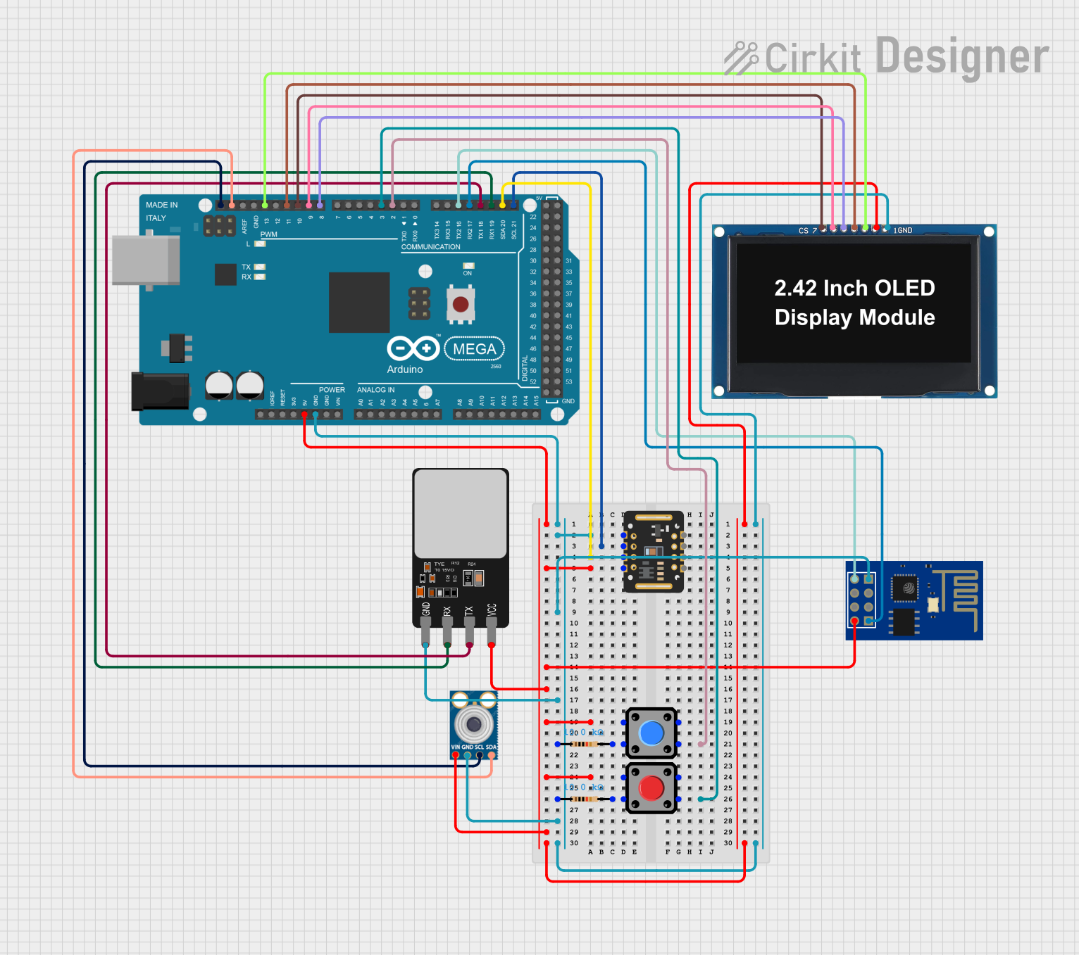
Circuit Documentation
Summary
This document provides a detailed overview of a circuit designed to interface various sensors and modules with an Arduino Mega 2560 microcontroller. The circuit includes a fingerprint scanner, an OLED display, two pushbuttons, a pair of resistors, an infrared temperature sensor (mlx90614), a pulse oximetry sensor (MAX30102), and an ESP8266 ESP-01 WiFi module. The Arduino Mega 2560 serves as the central processing unit, managing data communication between the sensors and the display, as well as handling wireless communication through the WiFi module.
Component List
Fingerprint Scanner
- Description: A sensor used to capture and process fingerprints.
- Pins: VCC, TX, RX, GND
Arduino Mega 2560
- Description: A microcontroller board based on the ATmega2560.
- Pins: Multiple digital and analog pins, power supply pins, and communication interface pins.
OLED Display 2.42"
- Description: A small display for visual output.
- Pins: GND, VCC, SCK, SDA, RES, DC, CS
Pushbutton (x2)
- Description: A simple switch mechanism for control of a circuit.
- Pins: Pin 1, Pin 2, Pin 3, Pin 4
Resistor (x2)
- Description: A passive two-terminal electrical component that implements electrical resistance as a circuit element.
- Value: 10,000 Ohms
mlx90614
- Description: An infrared thermometer for non-contact temperature measurements.
- Pins: SDA, SCL, GND, VIN
MAX30102
- Description: An integrated pulse oximetry and heart-rate monitor sensor solution.
- Pins: VIN, SDA, SCL, GND, RD, IRD, INT
ESP8266 ESP-01 WiFi Module
- Description: A self-contained SOC with integrated TCP/IP protocol stack that can give any microcontroller access to a WiFi network.
- Pins: TXD, CH_PD, RST, VCC, GND, GPIO_2, GPIO_0, RXD
Wiring Details
Fingerprint Scanner
- VCC: Connected to 5V power supply.
- TX: Connected to Arduino Mega 2560 (TX1).
- RX: Connected to Arduino Mega 2560 (RX1).
- GND: Connected to common ground.
Arduino Mega 2560
- GND: Common ground for all components.
- 5V: Power supply for components requiring 5V.
- D2 PWM: Connected to Pushbutton 1.
- D3 PWM: Connected to Pushbutton 2.
- D18/TX1: Connected to Fingerprint Scanner TX.
- D19/RX1: Connected to Fingerprint Scanner RX.
- D20/SDA, D21/SCL: Connected to MAX30102 and mlx90614 for I2C communication.
- D13 PWM: Connected to OLED Display SCK.
- D11 PWM: Connected to OLED Display SDA.
- D8 PWM: Connected to OLED Display RES.
- D9 PWM: Connected to OLED Display DC.
- D10 PWM: Connected to OLED Display CS.
- D16 PWM/TX2: Connected to ESP8266 ESP-01 WiFi Module TXD.
- D17 PWM/RX2: Connected to ESP8266 ESP-01 WiFi Module RXD.
OLED Display 2.42"
- GND: Connected to common ground.
- VCC: Connected to 5V power supply.
- SCK: Connected to Arduino Mega 2560 (D13 PWM).
- SDA: Connected to Arduino Mega 2560 (D11 PWM).
- RES: Connected to Arduino Mega 2560 (D8 PWM).
- DC: Connected to Arduino Mega 2560 (D9 PWM).
- CS: Connected to Arduino Mega 2560 (D10 PWM).
Pushbutton 1
- Pin 2: Connected to Arduino Mega 2560 (D2 PWM).
- Pin 1: Connected to Resistor 2.
Pushbutton 2
- Pin 2: Connected to Arduino Mega 2560 (D3 PWM).
- Pin 1: Connected to Resistor 1.
Resistor 1
- Pin 1: Connected to common ground.
- Pin 2: Connected to Pushbutton 2 (Pin 1).
Resistor 2
- Pin 1: Connected to common ground.
- Pin 2: Connected to Pushbutton 1 (Pin 1).
mlx90614
- SDA: Connected to Arduino Mega 2560 (SDA).
- SCL: Connected to Arduino Mega 2560 (SCL).
- GND: Connected to common ground.
- VIN: Connected to 5V power supply.
MAX30102
- VIN: Connected to 5V power supply.
- SDA: Connected to Arduino Mega 2560 (D20/SDA).
- SCL: Connected to Arduino Mega 2560 (D21/SCL).
- GND: Connected to common ground.
ESP8266 ESP-01 WiFi Module
- TXD: Connected to Arduino Mega 2560 (TX2).
- RXD: Connected to Arduino Mega 2560 (RX2).
- VCC: Connected to 5V power supply.
- GND: Connected to common ground.
Documented Code
Arduino Mega 2560 Code (sketch.ino)
void setup() {
  // put your setup code here, to run once:

}

void loop() {
  // put your main code here, to run repeatedly:

}
This code is a template for the Arduino Mega 2560. The setup() function is called once when the microcontroller is first powered on or reset. It is used to initialize the digital pins as input or output and to set up communication protocols. The loop() function is called repeatedly and contains the main logic of the program. It is here that the microcontroller will interact with the connected sensors, process the data, and control the OLED display and WiFi module. The actual implementation details will depend on the specific requirements of the application.