
Arduino UNO Traffic Light Control System with Pushbutton Cycling
View and Edit Project In Cirkit Designer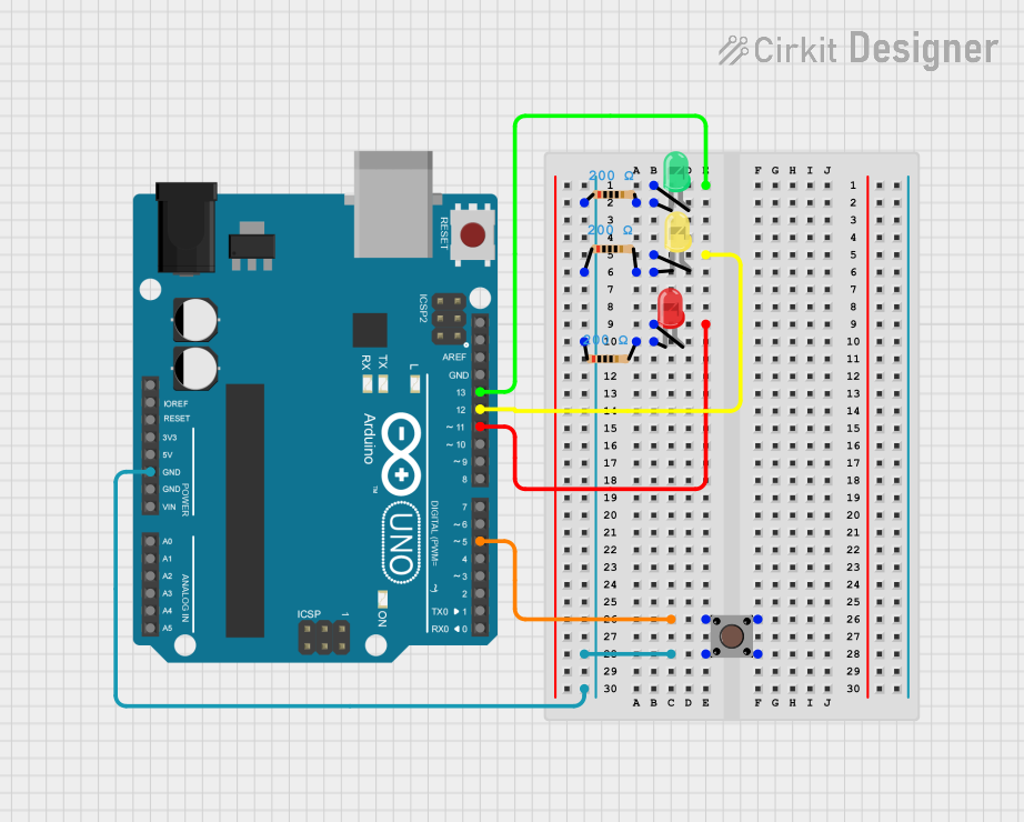
Traffic Light Control System Documentation
Summary
This document describes a simple traffic light control system implemented using an Arduino UNO microcontroller. The system controls three LEDs (red, yellow, and green) to simulate a traffic light. A pushbutton is used to cycle through the LEDs, changing the active light from red to yellow to green and back to red. The system is designed to be responsive to user input while preventing signal bouncing through debounce delays.
Component List
Arduino UNO
- Microcontroller board based on the ATmega328P
- It has 14 digital input/output pins, 6 analog inputs, a 16 MHz quartz crystal, a USB connection, a power jack, an ICSP header, and a reset button.
Resistor (200 Ohms)
- Three resistors with a resistance of 200 Ohms each
- Used to limit the current flowing through the LEDs to prevent damage
LED: Two Pin (Red)
- A red LED with two pins: anode and cathode
- Acts as the red signal in the traffic light system
LED: Two Pin (Green)
- A green LED with two pins: anode and cathode
- Acts as the green signal in the traffic light system
LED: Two Pin (Yellow)
- A yellow LED with two pins: anode and cathode
- Acts as the yellow signal in the traffic light system
Pushbutton
- A simple pushbutton with four pins: two for input and two for output
- Used to cycle through the traffic light system
Wiring Details
Arduino UNO
- D13 connected to the anode of the green LED
- D12 connected to the anode of the yellow LED
- D11 connected to the anode of the red LED
- D5 connected to the output of the pushbutton
- GND connected to one side of each resistor
Resistor (200 Ohms)
- One side connected to the GND of the Arduino UNO
- The other side connected to the cathode of the corresponding LED
LED: Two Pin (Red)
- Anode connected to D11 of the Arduino UNO
- Cathode connected to a 200 Ohm resistor
LED: Two Pin (Green)
- Anode connected to D13 of the Arduino UNO
- Cathode connected to a 200 Ohm resistor
LED: Two Pin (Yellow)
- Anode connected to D12 of the Arduino UNO
- Cathode connected to a 200 Ohm resistor
Pushbutton
- One input pin connected to the D5 of the Arduino UNO
- The other input pin connected to the GND of the Arduino UNO through a 200 Ohm resistor
Documented Code
/*
 * This Arduino sketch controls a traffic light system with red, yellow, and green LEDs.
 * Each time the button is pressed, the system cycles through the colors in the order:
 * red -> yellow -> green -> red.
 */

const int buttonPin = 5; // Pin connected to the pushbutton
const int redLEDPin = 11; // Pin connected to the red LED
const int yellowLEDPin = 12; // Pin connected to the yellow LED
const int greenLEDPin = 13; // Pin connected to the green LED

int buttonState = 0; // Variable for reading the pushbutton status
int currentLED = 0; // Variable to keep track of the current LED

void setup() {
  pinMode(buttonPin, INPUT); // Initialize the pushbutton pin as an input
  pinMode(redLEDPin, OUTPUT); // Initialize the red LED pin as an output
  pinMode(yellowLEDPin, OUTPUT); // Initialize the yellow LED pin as an output
  pinMode(greenLEDPin, OUTPUT); // Initialize the green LED pin as an output
  digitalWrite(redLEDPin, HIGH); // Start with the red LED on
}

void loop() {
  buttonState = digitalRead(buttonPin); // Read the state of the pushbutton
  if (buttonState == HIGH) { // Check if the button is pressed
    delay(50); // Debounce delay
    while (digitalRead(buttonPin) == HIGH); // Wait for button release
    delay(50); // Debounce delay
    cycleLED(); // Cycle to the next LED
  }
}

void cycleLED() {
  // Turn off all LEDs
  digitalWrite(redLEDPin, LOW);
  digitalWrite(yellowLEDPin, LOW);
  digitalWrite(greenLEDPin, LOW);
  // Cycle through the LEDs
  currentLED = (currentLED + 1) % 3;
  switch (currentLED) {
    case 0:
      digitalWrite(redLEDPin, HIGH); // Turn on the red LED
      break;
    case 1:
      digitalWrite(yellowLEDPin, HIGH); // Turn on the yellow LED
      break;
    case 2:
      digitalWrite(greenLEDPin, HIGH); // Turn on the green LED
      break;
  }
}
This code is designed to be uploaded to the Arduino UNO microcontroller. It initializes the pins connected to the LEDs and the pushbutton, and contains a main loop that checks for button presses to cycle through the LEDs. The cycleLED function manages which LED is turned on at any given time.