Cirkit Designer
Your all-in-one circuit design IDE
Home /
Project Documentation
Arduino UNO R4 WiFi Infrared Proximity Sensor Interface

Circuit Documentation
Summary of the Circuit
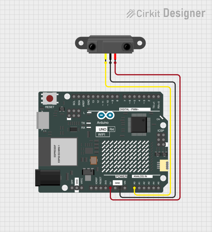
This circuit consists of an Arduino UNO R4 WiFi microcontroller board and an Infrared Proximity Sensor. The Arduino UNO R4 WiFi is responsible for controlling the behavior of the circuit, including reading the output from the Infrared Proximity Sensor and blinking an LED connected to one of its digital pins. The Infrared Proximity Sensor is used to detect the presence of an object within its range and outputs a signal that is read by the Arduino.
Component List
Arduino UNO R4 WiFi
- Description: A microcontroller board based on the ATmega328P with integrated WiFi capabilities.
- Purpose: Acts as the central processing unit of the circuit, reads sensor data, and controls the LED.
- Pins: OFF, GND, VRTC, IIC0_SCL, IIC0_SDA, 3V3, GPIO 41, GPIO 0, GPIO 42, GPIO 43, GPIO 44, BOOT, IOREF, RESET, 5V, VIN, A0, A1, A2, A3, A4, A5, RSPCKA, CIPO, COPI, D0/RX, D1/TX, D2, D3, D4, D5, D6, D7, D8, D9, D10, D11, D12, D13, AREF, SDA, SCL.
Infrared Proximity Sensor
- Description: A sensor that detects the presence of an object within a certain distance without any physical contact.
- Purpose: Provides a digital output signal to the Arduino when an object is detected within its proximity range.
- Pins: Vout, GND, Vcc.
Wiring Details
Arduino UNO R4 WiFi
- 5V connected to Infrared Proximity Sensor Vcc.
- GND connected to Infrared Proximity Sensor GND.
- A0 connected to Infrared Proximity Sensor Vout.
Infrared Proximity Sensor
- Vcc connected to Arduino UNO R4 WiFi 5V.
- GND connected to Arduino UNO R4 WiFi GND.
- Vout connected to Arduino UNO R4 WiFi A0.
Documented Code
Arduino UNO R4 WiFi - sketch.ino
/*
 * This Arduino sketch is designed to blink an LED connected to pin D8 of the
 * Arduino UNO R4 WiFi. The LED will turn on for 1 second and then turn off
 * for 1 second, repeatedly.
 */

void setup() {
  // Initialize digital pin D8 as an output.
  pinMode(13, OUTPUT);
}

void loop() {
  // Turn the LED on (HIGH is the voltage level)
  digitalWrite(13, HIGH);
  // Wait for a second
  delay(1000);
  // Turn the LED off by making the voltage LOW
  digitalWrite(13, LOW);
  // Wait for a second
  delay(1000);
}
Note: The code comments mention pin D8, but the code uses pin D13 for blinking the LED. Ensure that the LED is connected to pin D13 on the Arduino UNO R4 WiFi, or adjust the code to match the physical connection.