
Circuit Documentation
Summary
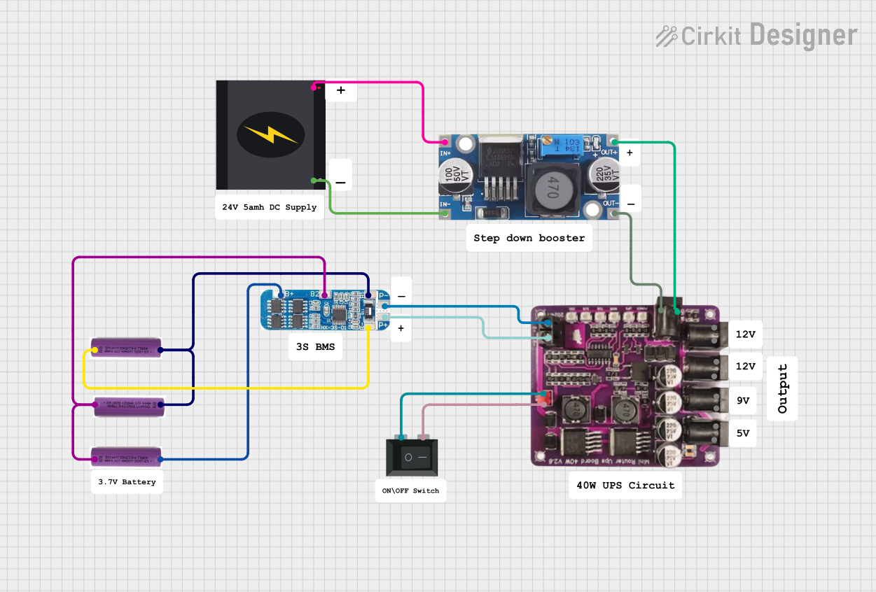
This document provides a detailed overview of a circuit that includes a Step Down Buck Converter, a Rocker Switch (SPST), a Battery Management System (BMS), a 40W UPS, three 3.7V batteries, and a 240V Power Source. The circuit is designed to manage power distribution and conversion from a high-voltage AC source to a lower DC voltage, with battery management and backup power capabilities.
Component List
Step Down Buck Converter
- Description: Converts high voltage DC input to a lower voltage DC output.
- Pins: IN +, IN - GND, OUT +, OUT - GND
Rocker Switch (SPST)
- Description: A single-pole single-throw switch used to control the connection between two points.
- Pins: 1, 2
Battery Management System (BMS)
- Description: Manages the charging and discharging of batteries to ensure safe operation.
- Pins: B+, B2, B1, B-, P -, P +
40W UPS
- Description: Provides uninterruptible power supply to ensure continuous power delivery.
- Pins: None
3.7V Battery
- Description: Provides a 3.7V DC power source.
- Pins: +, -
240V Power Source
- Description: Provides a 240V AC power source.
- Pins: Live, Neutral
Wiring Details
Step Down Buck Converter
- IN + is connected to Live of the 240V Power Source.
- IN - GND is connected to Neutral of the 240V Power Source.
- OUT + is connected to the 40W UPS.
- OUT - GND is connected to the 40W UPS.
Rocker Switch (SPST)
- Pin 1 is connected to the 40W UPS.
- Pin 2 is connected to the 40W UPS.
Battery Management System (BMS)
- B+ is connected to the + of the first 3.7V Battery.
- B2 is connected to the - of the first 3.7V Battery and the + of the second 3.7V Battery.
- B1 is connected to the + of the third 3.7V Battery and the - of the second 3.7V Battery.
- B- is connected to the - of the third 3.7V Battery.
- P - is connected to the 40W UPS.
- P + is connected to the 40W UPS.
40W UPS
- Connected to:
- OUT + and OUT - GND of the Step Down Buck Converter.
- Pin 1 and Pin 2 of the Rocker Switch (SPST).
- P - and P + of the Battery Management System (BMS).
3.7V Battery
First Battery:
- + is connected to B+ of the Battery Management System (BMS).
- - is connected to B2 of the Battery Management System (BMS).
Second Battery:
- + is connected to B2 of the Battery Management System (BMS).
- - is connected to B1 of the Battery Management System (BMS).
Third Battery:
- + is connected to B1 of the Battery Management System (BMS).
- - is connected to B- of the Battery Management System (BMS).
240V Power Source
- Live is connected to IN + of the Step Down Buck Converter.
- Neutral is connected to IN - GND of the Step Down Buck Converter.
Code
There is no embedded code provided for this circuit.
This documentation provides a comprehensive overview of the components and their interconnections within the circuit. Each component's role and wiring details are clearly outlined to facilitate understanding and troubleshooting.