Cirkit Designer
Your all-in-one circuit design IDE
Home /
Project Documentation
Raspberry Pi Controlled LED Array with Resistors
Circuit Documentation
Summary
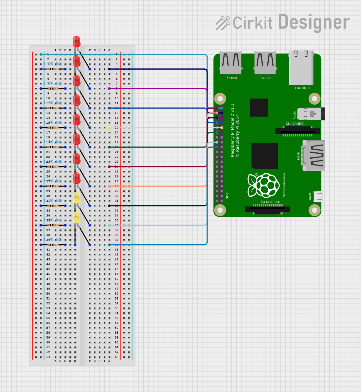
This circuit consists of multiple LEDs (both red and yellow) connected to a Raspberry Pi 2B. Each LED is connected in series with a 1000 Ohm resistor. The anodes of the LEDs are connected to various GPIO pins on the Raspberry Pi, while the cathodes are connected to the resistors, which are then connected to the ground (GND) pin of the Raspberry Pi.
Component List
LED: Two Pin (red)
- Description: A red LED with two pins: anode and cathode.
- Purpose: To emit red light when current flows through it.
LED: Two Pin (yellow)
- Description: A yellow LED with two pins: anode and cathode.
- Purpose: To emit yellow light when current flows through it.
Resistor
- Description: A resistor with two pins.
- Properties: 1000 Ohms resistance.
- Purpose: To limit the current flowing through the LEDs.
Raspberry Pi 2B
- Description: A single-board computer with multiple GPIO pins.
- Purpose: To control the LEDs by providing the necessary signals through its GPIO pins.
Wiring Details
LED: Two Pin (red)
- Anode connected to GPIO26 of the Raspberry Pi.
- Cathode connected to pin2 of a 1000 Ohm resistor.
- Anode connected to GPIO19 of the Raspberry Pi.
- Cathode connected to pin2 of a 1000 Ohm resistor.
- Anode connected to GPIO13 of the Raspberry Pi.
- Cathode connected to pin2 of a 1000 Ohm resistor.
- Anode connected to GPIO6 of the Raspberry Pi.
- Cathode connected to pin2 of a 1000 Ohm resistor.
- Anode connected to GPIO5 of the Raspberry Pi.
- Cathode connected to pin2 of a 1000 Ohm resistor.
- Anode connected to GPIO21 of the Raspberry Pi.
- Cathode connected to pin2 of a 1000 Ohm resistor.
- Anode connected to GPIO20 of the Raspberry Pi.
- Cathode connected to pin2 of a 1000 Ohm resistor.
- Anode connected to GPIO16 of the Raspberry Pi.
- Cathode connected to pin2 of a 1000 Ohm resistor.
LED: Two Pin (yellow)
- Anode connected to GPIO7 of the Raspberry Pi.
- Cathode connected to pin2 of a 1000 Ohm resistor.
- Anode connected to GPIO8 of the Raspberry Pi.
- Cathode connected to pin2 of a 1000 Ohm resistor.
Resistors
- Pin1 of all resistors connected to GND of the Raspberry Pi.
Raspberry Pi 2B
- GPIO26 connected to anode of a red LED.
- GPIO19 connected to anode of a red LED.
- GPIO13 connected to anode of a red LED.
- GPIO6 connected to anode of a red LED.
- GPIO5 connected to anode of a red LED.
- GPIO21 connected to anode of a red LED.
- GPIO20 connected to anode of a red LED.
- GPIO16 connected to anode of a red LED.
- GPIO7 connected to anode of a yellow LED.
- GPIO8 connected to anode of a yellow LED.
- GND connected to pin1 of all resistors.
Code
No code is provided for this circuit.