
Automated Peristaltic Pump Control System with Arduino and ESP32
View and Edit Project In Cirkit Designer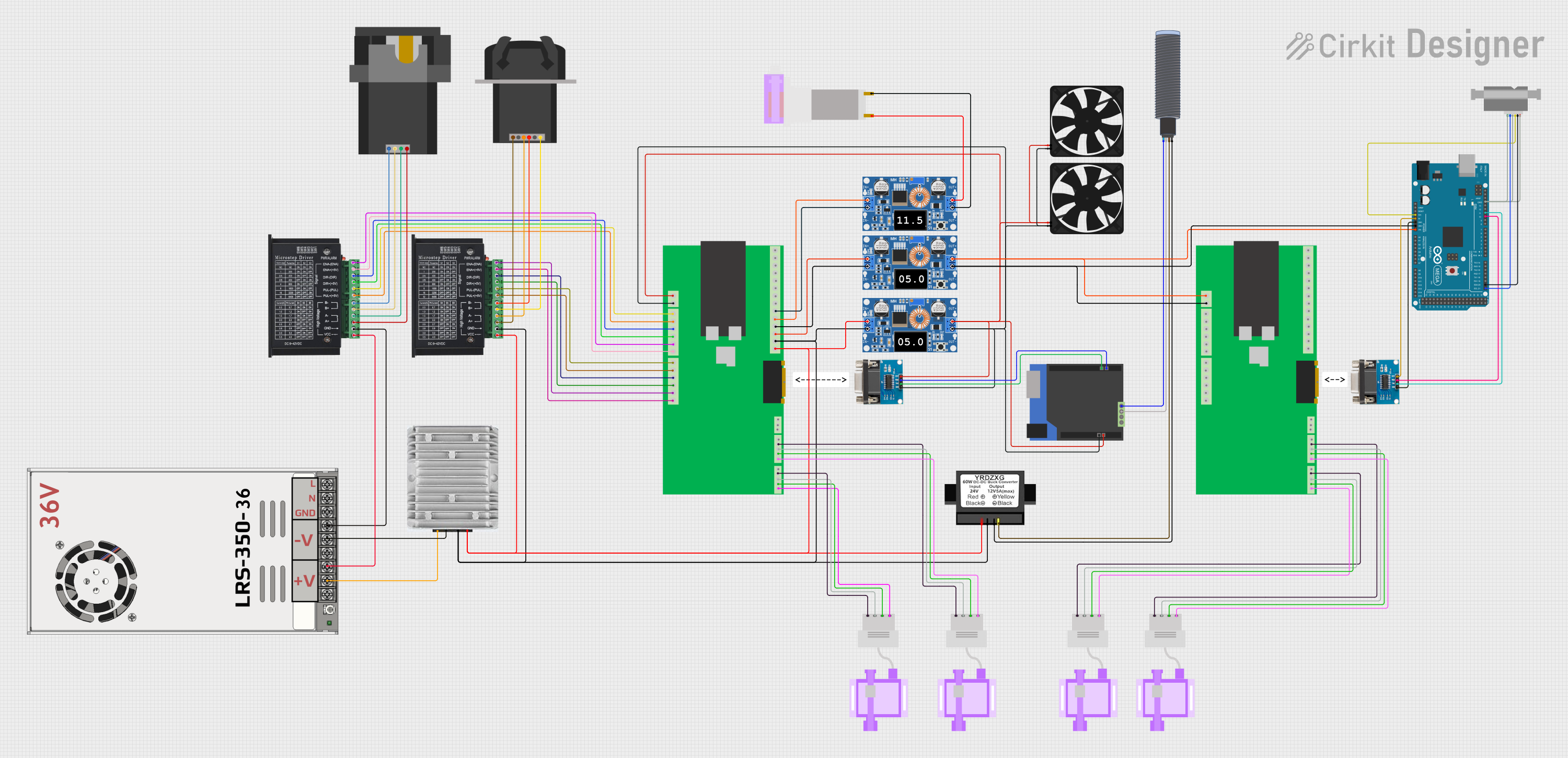
Circuit Documentation
Summary
This circuit is designed to control various components including motor drivers, peristaltic pumps, a power supply, voltage converters, sensors, and microcontrollers. The main power supply is a 48V unit which feeds into voltage converters to step down the voltage for different parts of the circuit. Motor drivers are used to control peristaltic pumps, and a microcontroller is used for overall control and data handling. Communication is facilitated by RS232 to TTL and RS485 interfaces. Sensing is done using pressure sensors and an ultrasonic sensor.
Component List
Power Supply
- MW LRS-350-48: A 48V power supply unit with outputs for +48V, -48V, and ground.
Voltage Converters
- 36 to 24 V Convertor: Steps down voltage from 36V to 24V.
- XL4015 5A DC Buck Step-down: A DC-DC converter that steps down voltage with a maximum current of 5A.
- 24 to 12 V Stepdown: Steps down voltage from 24V to 12V.
Motor Drivers
- tb6600 Micro Stepping Motor Driver: A driver for controlling stepper motors, with inputs for enable, direction, and pulse signals.
Pumps
- 313KB Peristaltic Pump: A type of pump used for moving fluids in a controlled manner.
- KPCS200 Peristaltic Pump: Another peristaltic pump for fluid control.
- KEF-HB1S10P Peristaltic Pump: A peristaltic pump with voltage input and ground.
Sensors
- URM14 Ultrasonic Sensor: An ultrasonic sensor for distance measurement.
- Pendotech Luer Lock In Line Pressure Sensor: A pressure sensor for monitoring fluid pressure in a line.
- Sensirion Flow Meter: A flow meter for measuring fluid flow rates.
Microcontrollers
- Arduino Mega 2560: A microcontroller board based on the ATmega2560 with numerous I/O pins.
- RS485 Shield on Arduino Leonardo: An RS485 communication shield mounted on an Arduino Leonardo.
- Custom PCB w/ ESP32: A custom-designed PCB that includes an ESP32 microcontroller for Wi-Fi and Bluetooth connectivity.
Communication Modules
- RS232 to TTL converter: A module for converting RS232 signals to TTL level signals.
Miscellaneous
- Fan: A cooling fan for thermal management.
Wiring Details
MW LRS-350-48
+48V outputto 36 to 24 V ConvertorV inand tb6600 Micro Stepping Motor DriverVCC-48V outputto 36 to 24 V ConvertorGDand tb6600 Micro Stepping Motor DriverGND
36 to 24 V Convertor
V outto Custom PCB w/ ESP3224 V Supply
tb6600 Micro Stepping Motor Driver
ENA-,ENA+,DIR-,DIR+,PUL-,PUL+connected to corresponding pins on Custom PCB w/ ESP32B-,B+,A-,A+connected to 313KB Peristaltic Pump and KPCS200 Peristaltic Pump
XL4015 5A DC Buck Step-down
- Multiple units stepping down to different voltages for various components such as the KEF-HB1S10P Peristaltic Pump, Fans, and the Arduino Mega 2560.
Custom PCB w/ ESP32
- Various connections to motor drivers, pressure sensors, and communication modules.
RS232 to TTL converter
- Connected to RS485 Shield on Arduino Leonardo and Arduino Mega 2560 for serial communication.
Arduino Mega 2560
- Connected to Sensirion Flow Meter and RS232 to TTL converter for data acquisition and control.
Sensirion Flow Meter
- Connected to Arduino Mega 2560 for flow rate measurements.
Fans
- Powered by XL4015 5A DC Buck Step-down converters for cooling.
Documented Code
Arduino Mega 2560 Code (sketch.ino)
void setup() {
  // put your setup code here, to run once:

}

void loop() {
  // put your main code here, to run repeatedly:

}
Note: The provided code for the Arduino Mega 2560 is a template with empty setup and loop functions. This code should be expanded with the necessary initialization and control logic to manage the connected devices and sensors.