
Circuit Documentation
Summary
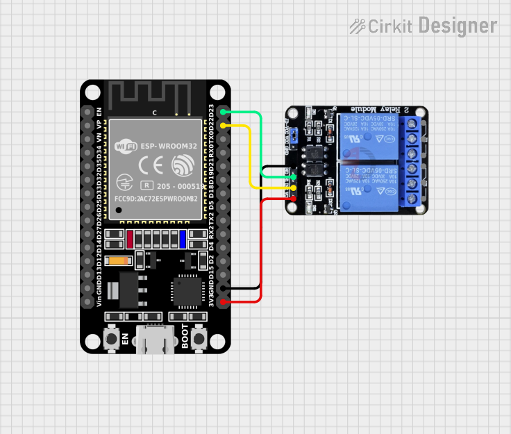
This document provides a detailed overview of a circuit that includes an ESP32 microcontroller and a two-channel relay module. The ESP32 is used to control the relay module, which can be used to switch external devices on and off. The document includes a list of components, wiring details, and any associated code.
Component List
ESP32 (30 pin)
- Description: A powerful microcontroller with integrated Wi-Fi and Bluetooth capabilities.
- Pins: EN, VP, VN, D34, D35, D32, D33, D25, D26, D27, D14, D12, D13, GND, Vin, D23, D22, TX0, RX0, D21, D19, D18, D5, TX2, RX2, D4, D2, D15, 3V3
- Purpose in Circuit: Acts as the main controller, sending signals to the relay module to control external devices.
Two Channel Relay 5v
- Description: A relay module that allows the ESP32 to control two separate circuits.
- Pins: VCC, IN2, IN1, GND, NC2, C2, NO2, NC1, C1, NO1
- Purpose in Circuit: Used to switch external devices on and off based on signals received from the ESP32.
Wiring Details
ESP32 (30 pin)
- D23: Connected to IN1 of the Two Channel Relay 5v
- D22: Connected to IN2 of the Two Channel Relay 5v
- GND: Connected to GND of the Two Channel Relay 5v
- 3V3: Connected to VCC of the Two Channel Relay 5v
Two Channel Relay 5v
- IN1: Connected to D23 of the ESP32
- IN2: Connected to D22 of the ESP32
- GND: Connected to GND of the ESP32
- VCC: Connected to 3V3 of the ESP32
Code
No code is provided for this circuit.
This document provides a comprehensive overview of the circuit, including the components used and their interconnections. The ESP32 microcontroller is used to control the two-channel relay module, allowing for the switching of external devices.