Cirkit Designer
Your all-in-one circuit design IDE
Home /
Project Documentation
Arduino-Based Multi-Sensor Environmental Monitoring System
Circuit Documentation
Summary
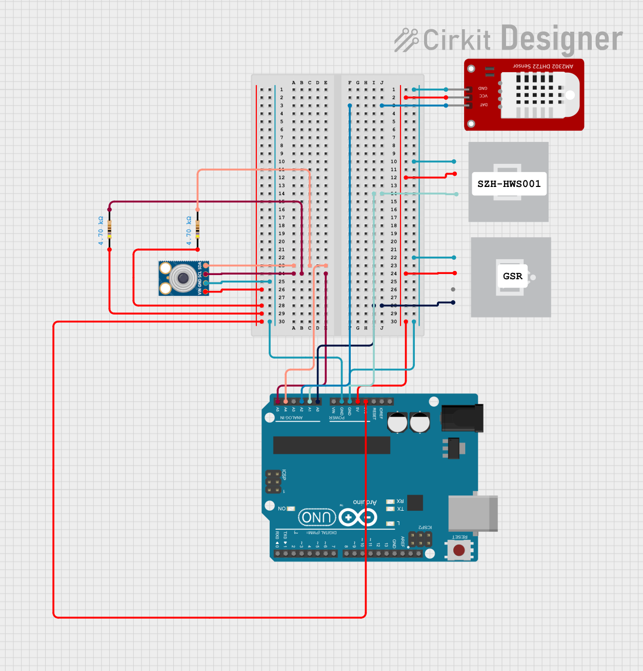
This document provides a detailed overview of a circuit that includes various sensors and an Arduino UNO microcontroller. The circuit is designed to interface with multiple sensors, including a DHT22 temperature and humidity sensor, an SZH-HWS001 sensor, an MLX90614 infrared temperature sensor, and a Grove GSR sensor. The Arduino UNO serves as the central microcontroller, managing data acquisition and processing from these sensors.
Component List
DHT22
- Description: Temperature and Humidity Sensor
- Pins: GND, VCC, DAT
SZH-HWS001
- Description: Sensor Module
- Pins: GND, 5V, DATA
MLX90614
- Description: Infrared Temperature Sensor
- Pins: SDA, SCL, GND, VIN
Arduino UNO
- Description: Microcontroller Board
- Pins: UNUSED, IOREF, Reset, 3.3V, 5V, GND, Vin, A0, A1, A2, A3, A4, A5, SCL, SDA, AREF, D13, D12, D11, D10, D9, D8, D7, D6, D5, D4, D3, D2, D1, D0
Grove GSR
- Description: Galvanic Skin Response Sensor
- Pins: GND, 5V, NC, A0
Resistor (4700 Ohms)
- Description: Resistor
- Pins: pin1, pin2
Wiring Details
DHT22
- GND: Connected to GND of Arduino UNO
- VCC: Connected to 5V of Arduino UNO
- DAT: Connected to A2 of Arduino UNO
SZH-HWS001
- GND: Connected to GND of Arduino UNO
- 5V: Connected to 5V of Arduino UNO
- DATA: Connected to A1 of Arduino UNO
MLX90614
- SDA: Connected to A4 of Arduino UNO via a 4700 Ohm resistor
- SCL: Connected to A5 of Arduino UNO via a 4700 Ohm resistor
- GND: Connected to GND of Arduino UNO
- VIN: Connected to 3.3V of Arduino UNO via two 4700 Ohm resistors
Arduino UNO
- A0: Connected to A0 of Grove GSR
- A1: Connected to DATA of SZH-HWS001
- A2: Connected to DAT of DHT22
- A4: Connected to SDA of MLX90614 via a 4700 Ohm resistor
- A5: Connected to SCL of MLX90614 via a 4700 Ohm resistor
- GND: Connected to GND of DHT22, SZH-HWS001, Grove GSR, and MLX90614
- 5V: Connected to VCC of DHT22, 5V of SZH-HWS001, and 5V of Grove GSR
- 3.3V: Connected to VIN of MLX90614 via two 4700 Ohm resistors
Grove GSR
- GND: Connected to GND of Arduino UNO
- 5V: Connected to 5V of Arduino UNO
- A0: Connected to A0 of Arduino UNO
Resistor (4700 Ohms)
- Resistor 1:
- pin1: Connected to 3.3V of Arduino UNO
- pin2: Connected to A4 of Arduino UNO and SDA of MLX90614
- Resistor 2:
- pin1: Connected to 3.3V of Arduino UNO
- pin2: Connected to A5 of Arduino UNO and SCL of MLX90614
Documented Code
Arduino UNO Code
void setup() {
  // put your setup code here, to run once:

}

void loop() {
  // put your main code here, to run repeatedly:

}
This code is a basic template for the Arduino UNO, with setup and loop functions defined but not yet implemented. The setup function runs once when the microcontroller is powered on or reset, and the loop function runs continuously after the setup function completes.