
Arduino Nano Based Weather Monitoring System with GSM and GPS
View and Edit Project In Cirkit Designer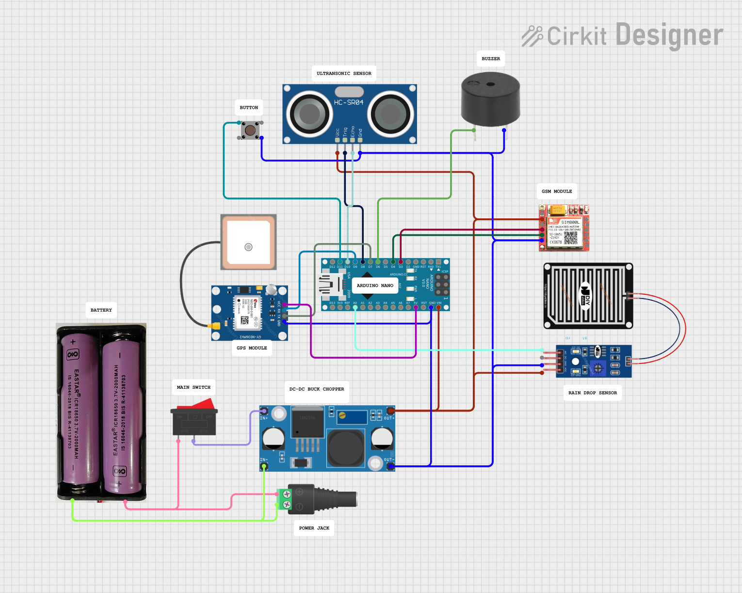
Circuit Documentation
Summary
This circuit integrates various components to perform multiple functions. It includes an Arduino Nano as the central microcontroller, interfaced with a SIM800L GSM module, a GPS NEO 6M module for location tracking, a rain sensor for detecting precipitation, an LM2956 buck converter for voltage regulation, an HC-SR04 ultrasonic sensor for distance measurement, a pushbutton for user input, a buzzer for audio feedback, and a rocker switch for power control. The circuit is powered by a 7.4V battery connected through a 2.1mm barrel jack with a terminal block.
Component List
- Arduino Nano: A compact microcontroller board based on the ATmega328P, featuring digital and analog I/O pins.
- SIM800L GSM Module: A cellular communication module for GSM networks, capable of sending SMS and making voice calls.
- GPS NEO 6M Module: A GPS receiver module for satellite-based positioning.
- Rain Sensor: An analog and digital sensor for detecting rainwater.
- LM2956 Buck Converter DC-DC: A step-down voltage regulator to convert higher voltage to a lower voltage.
- HC-SR04 Ultrasonic Sensor: A sensor for measuring distances using ultrasonic waves.
- Pushbutton: A simple switch mechanism for control or input.
- Buzzer: An electronic sounder that can produce a tone when powered.
- Rocker Switch: A switch for turning the power supply on and off.
- 7.4V Battery: A power source for the circuit.
- 2.1mm Barrel Jack with Terminal Block: A connector for attaching external power sources to the circuit.
Wiring Details
Arduino Nano
- D3 connected to SIM800L RXD
- D4 connected to SIM800L TXD
- D6 connected to Buzzer PIN
- D7 connected to GPS NEO 6M TX
- D8 connected to HC-SR04 Ultrasonic Sensor TRIG
- D9 connected to GPS NEO 6M RX
- D10 connected to HC-SR04 Ultrasonic Sensor ECHO
- D11/MOSI connected to Pushbutton Pin 2 (in)
- VIN connected to HC-SR04 Ultrasonic Sensor VCC, LM2956 Buck Converter DC-DC OUT+, and SIM800L VCC
- GND connected to HC-SR04 Ultrasonic Sensor GND, Pushbutton Pin 3 (out), Buzzer GND, LM2956 Buck Converter DC-DC OUT-, Rain Sensor GRD, GPS NEO 6M GND, and SIM800L GND
- 5V connected to GPS NEO 6M VCC
- A0 connected to Rain Sensor AO
SIM800L GSM Module
- RXD connected to Arduino Nano D3
- TXD connected to Arduino Nano D4
- VCC connected to Arduino Nano VIN
- GND connected to Arduino Nano GND
GPS NEO 6M Module
- TX connected to Arduino Nano D7
- RX connected to Arduino Nano D9
- VCC connected to Arduino Nano 5V
- GND connected to Arduino Nano GND
Rain Sensor
- AO connected to Arduino Nano A0
- VCC connected to LM2956 Buck Converter DC-DC OUT+
- GRD connected to Arduino Nano GND
LM2956 Buck Converter DC-DC
- OUT+ connected to Arduino Nano VIN, HC-SR04 Ultrasonic Sensor VCC, and Rain Sensor VCC
- OUT- connected to Arduino Nano GND
- IN+ connected to Rocker Switch 2
- IN- connected to 7.4V Battery -
HC-SR04 Ultrasonic Sensor
- TRIG connected to Arduino Nano D8
- ECHO connected to Arduino Nano D10
- VCC connected to Arduino Nano VIN
- GND connected to Arduino Nano GND
Pushbutton
- Pin 2 (in) connected to Arduino Nano D11/MOSI
- Pin 3 (out) connected to Arduino Nano GND
Buzzer
- PIN connected to Arduino Nano D6
- GND connected to Arduino Nano GND
Rocker Switch
- 1 connected to 7.4V Battery +
- 2 connected to LM2956 Buck Converter DC-DC IN+
7.4V Battery
- + connected to Rocker Switch 1
- - connected to LM2956 Buck Converter DC-DC IN-
2.1mm Barrel Jack with Terminal Block
- POS connected to 7.4V Battery +
- NEG connected to 7.4V Battery -
Documented Code
Arduino Nano Code (sketch.ino)
void setup() {
  // put your setup code here, to run once:

}

void loop() {
  // put your main code here, to run repeatedly:

}
Note: The provided code is a template and does not include specific functionality. It should be populated with the logic required to control the components based on the circuit's purpose.