
ESP32 and 16-Channel PWM Servo Driver-Based Wi-Fi Controlled Robotic Arm
View and Edit Project In Cirkit Designer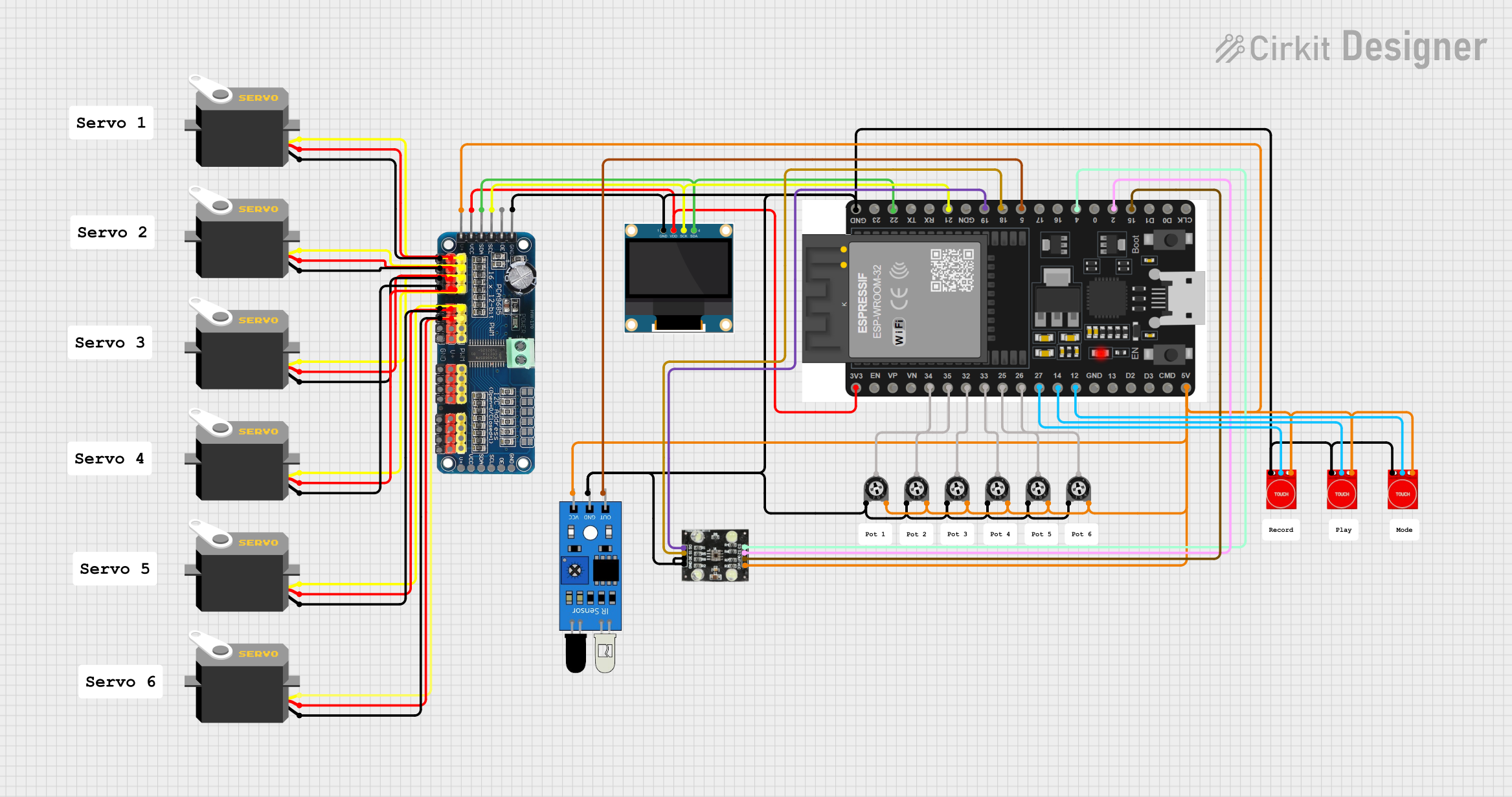
Circuit Documentation
Summary
This circuit is designed to control multiple servos using a 16-Channel PWM Servo Driver, an ESP32 microcontroller, and various sensors including IR sensors, touch sensors, and a color sensor (TCS230). The circuit also includes a 0.96" OLED display for visual feedback and several trimmer potentiometers for adjustable resistance.
Component List
16-Channel PWM Servo Driver
- Description: A driver to control up to 16 servos using PWM signals.
- Pins: V+, VCC, SDA, SCL, OE, GND, Vin+, Vin-, PWM1, PWM2, PWM3, PWM4, PWM5, PWM6, PWM7, PWM8, PWM9, PWM10, PWM11, PWM12, PWM13, PWM14, PWM15, PWM16
Servo
- Description: A standard servo motor.
- Pins: gnd, vcc, pulse
IR Sensor
- Description: An infrared sensor for detecting objects.
- Pins: out, gnd, vcc
ESP32 38 PINS
- Description: A microcontroller with Wi-Fi and Bluetooth capabilities.
- Pins: GND, 23, 22/SCL, 1, 2, 21/SDA, 19, 18, 5, 17/TX2, 16/RX2, 4, 0, 15, D1, D0, CLK, 3V3, EN, VP, VN, 34, 35, 32, 33, 25, 26, 27, 14, 12, 13, D2, D3, 11, 5V/VIN
0.96" OLED
- Description: A small OLED display for visual feedback.
- Pins: GND, VDD, SCK, SDA
TCS230
- Description: A color sensor.
- Pins: GND, OE, S1, S0, VCC, OUT, S2, S3
Trimmer Potentiometer
- Description: An adjustable resistor.
- Pins: leg1, wiper, leg2
- Properties: Resistance: 10000 Ohms
Touch Sensor TTP233
- Description: A touch sensor for detecting touch inputs.
- Pins: GND, I/O, VCC
Wiring Details
16-Channel PWM Servo Driver
- GND: Connected to GND of ESP32, IR Sensor, TCS230, and Trimmer Potentiometers.
- SDA: Connected to 22/SCL of ESP32 and SDA of OLED.
- SCL: Connected to 21/SDA of ESP32 and SCK of OLED.
- VCC: Connected to 3V3 of ESP32 and VDD of OLED.
- V+: Connected to 5V/VIN of ESP32, VCC of TCS230, VCC of IR Sensor, and VCC of Touch Sensors.
- PWM1: Connected to pulse of Servo 1.
- PWM2: Connected to pulse of Servo 2.
- PWM3: Connected to pulse of Servo 3.
- PWM4: Connected to pulse of Servo 4.
- PWM5: Connected to pulse of Servo 5.
- PWM6: Connected to pulse of Servo 6.
Servo
- gnd: Connected to GND of 16-Channel PWM Servo Driver.
- vcc: Connected to V+ of 16-Channel PWM Servo Driver.
- pulse: Connected to PWM pins of 16-Channel PWM Servo Driver.
IR Sensor
- gnd: Connected to GND of 16-Channel PWM Servo Driver.
- vcc: Connected to V+ of 16-Channel PWM Servo Driver.
- out: Connected to pin 5 of ESP32.
ESP32 38 PINS
- GND: Connected to GND of 16-Channel PWM Servo Driver, IR Sensor, TCS230, and Trimmer Potentiometers.
- 22/SCL: Connected to SDA of 16-Channel PWM Servo Driver and SDA of OLED.
- 21/SDA: Connected to SCL of 16-Channel PWM Servo Driver and SCK of OLED.
- 3V3: Connected to VCC of 16-Channel PWM Servo Driver and VDD of OLED.
- 5V/VIN: Connected to V+ of 16-Channel PWM Servo Driver, VCC of TCS230, VCC of IR Sensor, and VCC of Touch Sensors.
- 19: Connected to S0 of TCS230.
- 18: Connected to S1 of TCS230.
- 4: Connected to S3 of TCS230.
- 2: Connected to S2 of TCS230.
- 15: Connected to OUT of TCS230.
- 34: Connected to wiper of Trimmer Potentiometer 1.
- 35: Connected to wiper of Trimmer Potentiometer 2.
- 32: Connected to wiper of Trimmer Potentiometer 3.
- 33: Connected to wiper of Trimmer Potentiometer 4.
- 25: Connected to wiper of Trimmer Potentiometer 5.
- 26: Connected to wiper of Trimmer Potentiometer 6.
- 27: Connected to I/O of Touch Sensor 1.
- 14: Connected to I/O of Touch Sensor 2.
- 12: Connected to I/O of Touch Sensor 3.
0.96" OLED
- GND: Connected to GND of 16-Channel PWM Servo Driver.
- VDD: Connected to 3V3 of ESP32.
- SCK: Connected to SCL of 16-Channel PWM Servo Driver.
- SDA: Connected to SDA of 16-Channel PWM Servo Driver.
TCS230
- GND: Connected to GND of 16-Channel PWM Servo Driver.
- OE: Connected to GND of 16-Channel PWM Servo Driver.
- S0: Connected to pin 19 of ESP32.
- S1: Connected to pin 18 of ESP32.
- S2: Connected to pin 2 of ESP32.
- S3: Connected to pin 4 of ESP32.
- VCC: Connected to V+ of 16-Channel PWM Servo Driver.
- OUT: Connected to pin 15 of ESP32.
Trimmer Potentiometer
- leg1: Connected to GND of 16-Channel PWM Servo Driver.
- wiper: Connected to pins 34, 35, 32, 33, 25, and 26 of ESP32.
- leg2: Connected to V+ of 16-Channel PWM Servo Driver.
Touch Sensor TTP233
- GND: Connected to GND of 16-Channel PWM Servo Driver.
- I/O: Connected to pins 27, 14, and 12 of ESP32.
- VCC: Connected to V+ of 16-Channel PWM Servo Driver.
Code Documentation
ESP32 Code
sketch.ino
void setup() {
  // put your setup code here, to run once:

}

void loop() {
  // put your main code here, to run repeatedly:

}
documentation.txt
This documentation provides a comprehensive overview of the circuit, including a summary, component list, wiring details, and code documentation. Each component is described, and its connections are detailed to ensure clarity and ease of understanding.