Cirkit Designer
Your all-in-one circuit design IDE
Home /
Project Documentation
Arduino UNO Light-Sensitive Servo Control with LED Indicator
Circuit Documentation
Summary
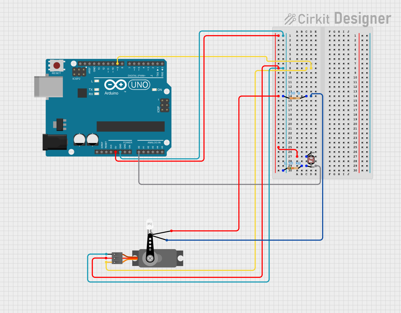
This circuit involves an Arduino UNO microcontroller, a servo motor, an LED, a photocell (LDR), and two resistors. The Arduino UNO controls the servo motor and reads the photocell's resistance to adjust the LED's brightness. The circuit is powered by the Arduino's 5V supply.
Component List
Arduino UNO
- Description: A microcontroller board based on the ATmega328P.
- Pins: UNUSED, IOREF, Reset, 3.3V, 5V, GND, Vin, A0, A1, A2, A3, A4, A5, SCL, SDA, AREF, D13, D12, D11, D10, D9, D8, D7, D6, D5, D4, D3, D2, D1, D0
Servo
- Description: A small motor with a feedback mechanism for precise control.
- Pins: GND, VCC, PWM
LED: Two Pin (white)
- Description: A white LED with two pins.
- Pins: cathode, anode
Resistor (330 Ohms)
- Description: A resistor with a resistance of 330 Ohms.
- Pins: pin1, pin2
Photocell (LDR)
- Description: A light-dependent resistor that changes resistance based on light intensity.
- Pins: pin 0, pin 1
Resistor (1500 Ohms)
- Description: A resistor with a resistance of 1500 Ohms.
- Pins: pin1, pin2
Wiring Details
Arduino UNO
5V connected to:
- Servo (VCC)
- LED (anode)
- Photocell (pin 1)
GND connected to:
- Resistor (330 Ohms) (pin1)
- Resistor (1500 Ohms) (pin1)
- Servo (GND)
D9 connected to:
- Servo (PWM)
A0 connected to:
- Photocell (pin 0)
- Resistor (1500 Ohms) (pin2)
Servo
VCC connected to:
- Arduino UNO (5V)
GND connected to:
- Arduino UNO (GND)
PWM connected to:
- Arduino UNO (D9)
LED: Two Pin (white)
anode connected to:
- Arduino UNO (5V)
cathode connected to:
- Resistor (330 Ohms) (pin2)
Resistor (330 Ohms)
pin1 connected to:
- Arduino UNO (GND)
pin2 connected to:
- LED (cathode)
Photocell (LDR)
pin 0 connected to:
- Resistor (1500 Ohms) (pin2)
- Arduino UNO (A0)
pin 1 connected to:
- Arduino UNO (5V)
Resistor (1500 Ohms)
pin1 connected to:
- Arduino UNO (GND)
pin2 connected to:
- Photocell (pin 0)
- Arduino UNO (A0)
Documented Code
sketch.ino
void setup() {
  // put your setup code here, to run once:

}

void loop() {
  // put your main code here, to run repeatedly:

}
documentation.txt