
Arduino UNO Password-Protected Servo Lock with LED Indicators
View and Edit Project In Cirkit Designer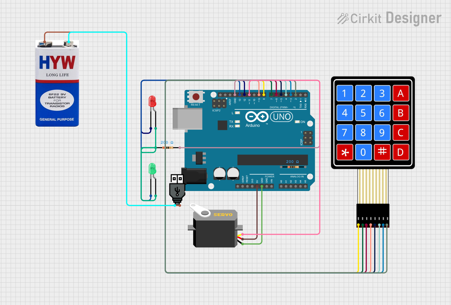
Circuit Documentation
Summary
This circuit is designed to control a servo motor and two LEDs using an Arduino UNO microcontroller. It also includes a 4x4 membrane matrix keypad for user input. The circuit is powered by a 9V battery and USB power. The red and green LEDs indicate the lock and unlock status, respectively, and the servo motor moves based on the keypad input.
Component List
Arduino UNO
- Description: Microcontroller board based on the ATmega328P.
- Pins: UNUSED, IOREF, Reset, 3.3V, 5V, GND, Vin, A0, A1, A2, A3, A4, A5, SCL, SDA, AREF, D13, D12, D11, D10, D9, D8, D7, D6, D5, D4, D3, D2, D1, D0
LED: Two Pin (red)
- Description: Red LED with two pins.
- Pins: cathode, anode
LED: Two Pin (green)
- Description: Green LED with two pins.
- Pins: cathode, anode
Servo
- Description: Servo motor with three pins.
- Pins: gnd, vcc, pulse
4X4 Membrane Matrix Keypad
- Description: Keypad with 4 rows and 4 columns.
- Pins: R1, R2, R3, R4, C1, C2, C3, C4
Resistor (200 Ohms)
- Description: Resistor with 200 Ohms resistance.
- Pins: pin1, pin2
9V battery
- Description: 9V battery for power supply.
- Pins: +, -
USB power
- Description: USB power supply.
- Pins: +, -
Wiring Details
Arduino UNO
- 5V connected to Servo vcc
- GND connected to Servo gnd
- GND connected to Resistor pin2
- D13 connected to Green LED cathode
- D12 connected to Red LED cathode
- D11 connected to Servo pulse
- D9 connected to Keypad R4
- D8 connected to Keypad R1
- D7 connected to Keypad R2
- D6 connected to Keypad R3
- D5 connected to Keypad C1
- D4 connected to Keypad C2
- D3 connected to Keypad C3
- D2 connected to Keypad C4
LED: Two Pin (red)
- cathode connected to Arduino UNO D12
- anode connected to Green LED anode and Resistor pin1
LED: Two Pin (green)
- cathode connected to Arduino UNO D13
- anode connected to Red LED anode and Resistor pin1
Servo
- vcc connected to Arduino UNO 5V
- gnd connected to Arduino UNO GND
- pulse connected to Arduino UNO D11
4X4 Membrane Matrix Keypad
- R1 connected to Arduino UNO D8
- R2 connected to Arduino UNO D7
- R3 connected to Arduino UNO D6
- R4 connected to Arduino UNO D9
- C1 connected to Arduino UNO D5
- C2 connected to Arduino UNO D4
- C3 connected to Arduino UNO D3
- C4 connected to Arduino UNO D2
Resistor (200 Ohms)
- pin1 connected to Red LED anode and Green LED anode
- pin2 connected to Arduino UNO GND
9V battery
- + connected to USB power +
- - connected to USB power -
USB power
- + connected to 9V battery +
- - connected to 9V battery -
Documented Code
Arduino UNO Code
#include <Servo.h>
#include <Keypad.h>

Servo ServoMotor;
char*  password = "427";  // change the password here, just pick any 3 numbers
int  position = 0;
const byte ROWS = 4;
const byte COLS = 4;
char keys[ROWS][COLS]  = {
  {'1','2','3','A'},
  {'4','5','6','B'},
  {'7','8','9','C'},
  {'*','0','#','D'}
};

byte  rowPins[ROWS] = { 8, 7, 6, 9 };
byte colPins[COLS] = { 5, 4, 3, 2 };
Keypad  keypad = Keypad( makeKeymap(keys), rowPins, colPins, ROWS, COLS );
int RedpinLock  = 12;
int GreenpinUnlock = 13;

void setup()
{
  pinMode(RedpinLock,  OUTPUT);
  pinMode(GreenpinUnlock, OUTPUT);
  ServoMotor.attach(11);
  LockedPosition(true);
}

void  loop()
{
  char key = keypad.getKey();
  if (key == '*' || key == '#')
  {
    position  = 0;
    LockedPosition(true);
  }
  if (key == password[position])
  {
    position  ++;
  }
  if (position == 3)
  {
    LockedPosition(false);
  }
  delay(100);
}

void  LockedPosition(int locked)
{
  if (locked)
  {
    digitalWrite(RedpinLock,  HIGH);
    digitalWrite(GreenpinUnlock, LOW);
    ServoMotor.write(11);
  }
  else
  {
    digitalWrite(RedpinLock,  LOW);
    digitalWrite(GreenpinUnlock, HIGH);
    ServoMotor.write(90);
  }
}
4X4 Membrane Matrix Keypad Code
void setup() {
  // put your setup code here, to run once:
}

void loop() {
  // put your main code here, to run repeatedly:
}
This documentation provides a comprehensive overview of the circuit, including the components used, their wiring details, and the code running on the microcontrollers.