Arduino-Controlled RGB LED Strip with Pushbutton Color Change
Circuit Documentation
Summary
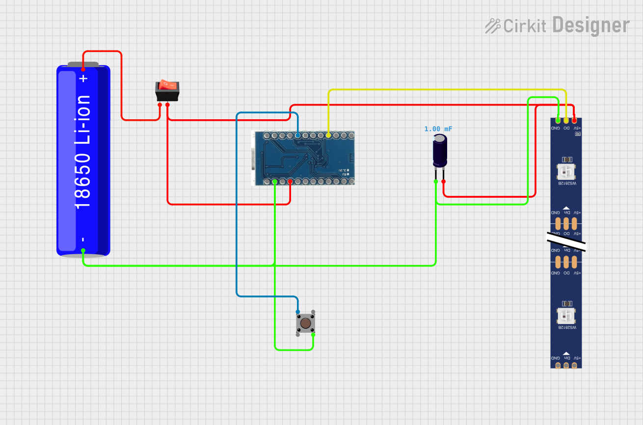
This circuit is designed to control a WS2812 RGB LED strip using an Arduino Micro Pro microcontroller. The circuit includes a pushbutton for user input, a rocker switch as a power control mechanism, an electrolytic capacitor for voltage smoothing, and a 18650 Li-ion battery as the power source. The LED strip can display a variety of colors, and the color can be changed by pressing the pushbutton.
Component List
Arduino Micro Pro
- Microcontroller board based on the ATmega32U4
- Operates at 5V
- Features digital and analog I/O pins
18650 Li-ion Battery
- Rechargeable battery
- Provides power to the circuit
Rocker Switch
- Acts as an on/off switch for the circuit
- Controls the power flow from the battery
Electrolytic Capacitor
- Capacitance: 0.001 Farads
- Used for voltage smoothing across the power supply
WS2812 RGB LED Strip
- Contains multiple RGB LEDs that can be individually controlled
- Requires a single data line for control
Pushbutton
- Provides user input to the microcontroller
- Used to change the color of the LED strip
Wiring Details
Arduino Micro Pro
VCCconnected to the positive side of the power supply through the rocker switchGNDconnected to the negative side of the power supply- Digital pin
6connected to theDINpin of the WS2812 RGB LED strip - Digital pin
2connected to one side of the pushbutton
18650 Li-ion Battery
+connected to the input of the rocker switch-connected to the common ground of the circuit
Rocker Switch
inputconnected to the positive terminal of the 18650 Li-ion Batteryoutputconnected to theVCCof the Arduino Micro Pro and the5Vpin of the WS2812 RGB LED strip
Electrolytic Capacitor
+connected to the positive side of the power supply-connected to the common ground of the circuit
WS2812 RGB LED Strip
5Vconnected to the positive side of the power supply through the rocker switchGNDconnected to the common ground of the circuitDINconnected to digital pin6on the Arduino Micro Pro
Pushbutton
- One side connected to digital pin
2on the Arduino Micro Pro - The other side connected to the common ground of the circuit
Documented Code
Arduino Micro Pro Code
#include <Adafruit_NeoPixel.h>

// Pin Definitions
#define BUTTON_PIN 2       // Pin connected to the button
#define LED_PIN 6          // Pin connected to the Neopixel data input
#define NUM_PIXELS 30      // Total number of LEDs on the Neopixel strip
#define ACTIVE_PIXELS 28   // Number of LEDs to glow

// Neopixel object
Adafruit_NeoPixel strip = Adafruit_NeoPixel(NUM_PIXELS, LED_PIN, NEO_GRB + NEO_KHZ800);

// Variables for color and button state
int currentColorIndex = 0;  // Index of the current color
bool buttonPressed = false;
bool lastButtonState = HIGH;

// Function to generate a random color
uint32_t randomColor() {
  return strip.Color(random(0, 256), random(0, 256), random(0, 256));
}

// Array of 12 predefined colors (RGB values)
uint32_t colors[] = {
  strip.Color(255, 0, 0),    // Red
  strip.Color(0, 255, 0),    // Green
  strip.Color(0, 0, 255),    // Blue
  strip.Color(255, 255, 0),  // Yellow
  strip.Color(0, 255, 255),  // Cyan
  strip.Color(255, 0, 255),  // Magenta
  strip.Color(255, 165, 0),  // Orange
  strip.Color(128, 0, 128),  // Purple
  strip.Color(75, 0, 130),   // Indigo
  0,                         // Placeholder for random colors (set later)
  strip.Color(255, 105, 180),// Pink
  strip.Color(255, 255, 255) // White
};

void setup() {
  pinMode(BUTTON_PIN, INPUT_PULLUP);  // Set button pin as input with internal pull-up resistor
  strip.begin();                      // Initialize the Neopixel strip
  strip.show();                       // Initialize all pixels to 'off'
  randomSeed(analogRead(0));          // Seed the random number generator
}

void loop() {
  // Read the state of the button
  bool buttonState = digitalRead(BUTTON_PIN);

  // Detect button press (transition from HIGH to LOW)
  if (buttonState == LOW && lastButtonState == HIGH) {
    buttonPressed = true;
  } else {
    buttonPressed = false;
  }

  // When the button is pressed, change the color
  if (buttonPressed) {
    currentColorIndex = (currentColorIndex + 1) % 12;  // Cycle through 12 colors
    if (currentColorIndex == 9) {
      setRandomStripColors();  // Set each LED to a random color
    } else {
      setStripColor(colors[currentColorIndex]);  // Set the new color on the strip
    }
  }

  // Update the last button state
  lastButtonState = buttonState;
}

// Function to set the color on the first 28 LEDs
void setStripColor(uint32_t color) {
  for (int i = 0; i < ACTIVE_PIXELS; i++) {
    strip.setPixelColor(i, color);
  }
  strip.show();  // Update the strip to display the color
}

// Function to set each of the first 28 LEDs to a different random color
void setRandomStripColors() {
  for (int i = 0; i < ACTIVE_PIXELS; i++) {
    strip.setPixelColor(i, randomColor());  // Assign a random color to each LED
  }
  strip.show();  // Update the strip to display the colors
}
This code is responsible for controlling the WS2812 RGB LED strip. It initializes the strip and sets up the button for user input. When the button is pressed, the color of the LED strip changes. There are 12 predefined colors, and one option to set random colors for each LED. The setStripColor function sets the entire strip to one color, while the setRandomStripColors function assigns a random color to each LED.