
ESP32-Based Smart Lock System with GPS and Fingerprint Scanner
View and Edit Project In Cirkit Designer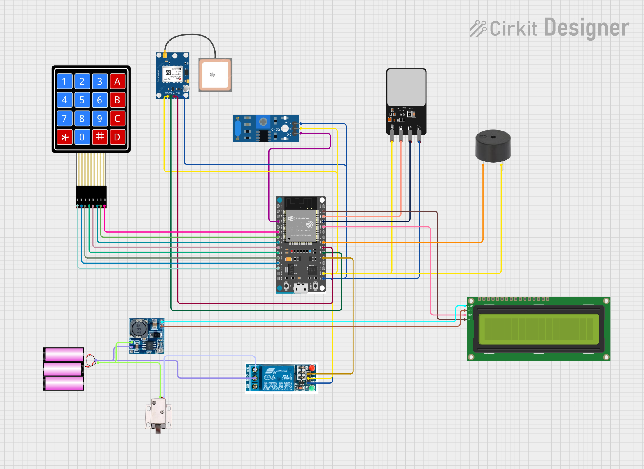
Circuit Documentation
Summary
This circuit is designed to integrate various sensors and actuators with an ESP32 microcontroller. The system includes a 16x2 I2C LCD for display, a GPS module for location tracking, a fingerprint scanner for biometric authentication, a buzzer for audio alerts, a solenoid lock for physical security, a vibration sensor for motion detection, a 5V relay for controlling high-power devices, and a 4x4 membrane matrix keypad for user input. The circuit is powered by a 12V battery, with a step-down module to provide the necessary voltages for different components.
Component List
16x2 I2C LCD
- Pins: GND, VCC, SDA, SCL
- Description: A 16x2 character LCD display with I2C interface.
- Purpose: To display information to the user.
GPS NEO 6M
- Pins: VCC, RX, TX, GND
- Description: A GPS module for location tracking.
- Purpose: To provide GPS coordinates.
Fingerprint Scanner
- Pins: VCC, TX, RX, GND
- Description: A biometric sensor for fingerprint recognition.
- Purpose: To authenticate users.
Buzzer
- Pins: PIN, GND
- Description: An audio alert device.
- Purpose: To provide audio feedback and alerts.
12V Solenoid Lock
- Pins: VCC, GND
- Description: An electronic lock.
- Purpose: To control access.
SW-420 Vibration Sensor
- Pins: VCC, Ground, Digital output
- Description: A sensor to detect vibrations.
- Purpose: To detect motion or vibrations.
5V Relay
- Pins: Normally Open, Common terminal, Normally Closed, In, GND, VCC
- Description: A relay module to control high-power devices.
- Purpose: To switch high-power devices on and off.
4X4 Membrane Matrix Keypad
- Pins: R1, R2, R3, R4, C1, C2, C3, C4
- Description: A 4x4 matrix keypad.
- Purpose: To provide user input.
ESP32 Devkit V1
- Pins: 3V3, GND, D15, D2, D4, RX2, TX2, D5, D18, D19, D21, RX0, TX0, D22, D23, EN, VP, VN, D34, D35, D32, D33, D25, D26, D27, D14, D12, D13, VIN
- Description: A development board based on the ESP32 microcontroller.
- Purpose: To control the entire system.
Step Down Module
- Pins: 24v IN+, GND, 12v IN+, 5v OUT+, 5v OUT-
- Description: A voltage regulator module.
- Purpose: To step down voltage from 12V to 5V.
Battery 12V
- Pins: +, -
- Description: A 12V battery.
- Purpose: To power the circuit.
Wiring Details
16x2 I2C LCD
- GND connected to Step Down Module 5v OUT-
- VCC connected to Step Down Module 5v OUT+
- SDA connected to ESP32 Devkit V1 D21
- SCL connected to ESP32 Devkit V1 D22
GPS NEO 6M
- VCC connected to 5V Relay VCC
- RX connected to ESP32 Devkit V1 TX2
- TX connected to ESP32 Devkit V1 RX2
- GND connected to 5V Relay GND
Fingerprint Scanner
- VCC connected to 5V Relay VCC
- TX connected to ESP32 Devkit V1 RX0
- RX connected to ESP32 Devkit V1 TX0
- GND connected to 5V Relay GND
Buzzer
- PIN connected to ESP32 Devkit V1 D5
- GND connected to 5V Relay GND
12V Solenoid Lock
- VCC connected to 5V Relay Normally Open
- GND connected to Battery 12V -
SW-420 Vibration Sensor
- VCC connected to 5V Relay VCC
- Ground connected to 5V Relay GND
- Digital output connected to ESP32 Devkit V1 D34
5V Relay
- Normally Open connected to 12V Solenoid Lock VCC
- Common terminal connected to Battery 12V +
- In connected to ESP32 Devkit V1 D4
- GND connected to Battery 12V -
- VCC connected to ESP32 Devkit V1 3V3
4X4 Membrane Matrix Keypad
- R1 connected to ESP32 Devkit V1 D13
- R2 connected to ESP32 Devkit V1 D12
- R3 connected to ESP32 Devkit V1 D14
- R4 connected to ESP32 Devkit V1 D27
- C1 connected to ESP32 Devkit V1 D26
- C2 connected to ESP32 Devkit V1 D25
- C3 connected to ESP32 Devkit V1 D33
- C4 connected to ESP32 Devkit V1 D32
ESP32 Devkit V1
- 3V3 connected to 5V Relay VCC
- GND connected to 5V Relay GND
- D21 connected to 16x2 I2C LCD SDA
- D22 connected to 16x2 I2C LCD SCL
- TX2 connected to GPS NEO 6M RX
- RX2 connected to GPS NEO 6M TX
- RX0 connected to Fingerprint Scanner TX
- TX0 connected to Fingerprint Scanner RX
- D5 connected to Buzzer PIN
- D4 connected to 5V Relay In
- D34 connected to SW-420 Vibration Sensor Digital output
- D13 connected to 4X4 Membrane Matrix Keypad R1
- D12 connected to 4X4 Membrane Matrix Keypad R2
- D14 connected to 4X4 Membrane Matrix Keypad R3
- D27 connected to 4X4 Membrane Matrix Keypad R4
- D26 connected to 4X4 Membrane Matrix Keypad C1
- D25 connected to 4X4 Membrane Matrix Keypad C2
- D33 connected to 4X4 Membrane Matrix Keypad C3
- D32 connected to 4X4 Membrane Matrix Keypad C4
Step Down Module
- 24v IN+ not connected
- GND connected to Battery 12V -
- 12v IN+ connected to Battery 12V +
- 5v OUT+ connected to 16x2 I2C LCD VCC
- 5v OUT- connected to 16x2 I2C LCD GND
Battery 12V
- + connected to 5V Relay Common terminal
- - connected to 5V Relay GND
Documented Code
/*
Code Last Version Project Microcontroller & Microprossessor
- Aslam Azharan Wade Laode  (235150307111029)
- Evan Rayhandra Gerard     (235150307111034)
- Timothy Bertu Pasaribu    (235150301111027)
*/

/* LIBRARY */
#include <Arduino.h>
#include <WiFi.h>
#include <HTTPClient.h>
#include <Wire.h>
#include <Keypad.h>
#include <TinyGPSPlus.h>
#include <HardwareSerial.h>
#include <SoftwareSerial.h>
#include <LiquidCrystal_I2C.h>
#include "time.h"

/* Keypad Rows & Collums */
#define ROWS 4
#define COLS 4
/* PIN RX2 & TX2 */
#define RXD2 16
#define TXD2 17

/* GPS SETUP */
HardwareSerial gpsSerial(2);
TinyGPSPlus gps;

/* TIME SETUP