Battery-Powered ESP32-C3 Interactive Control Panel
Circuit Documentation
Summary
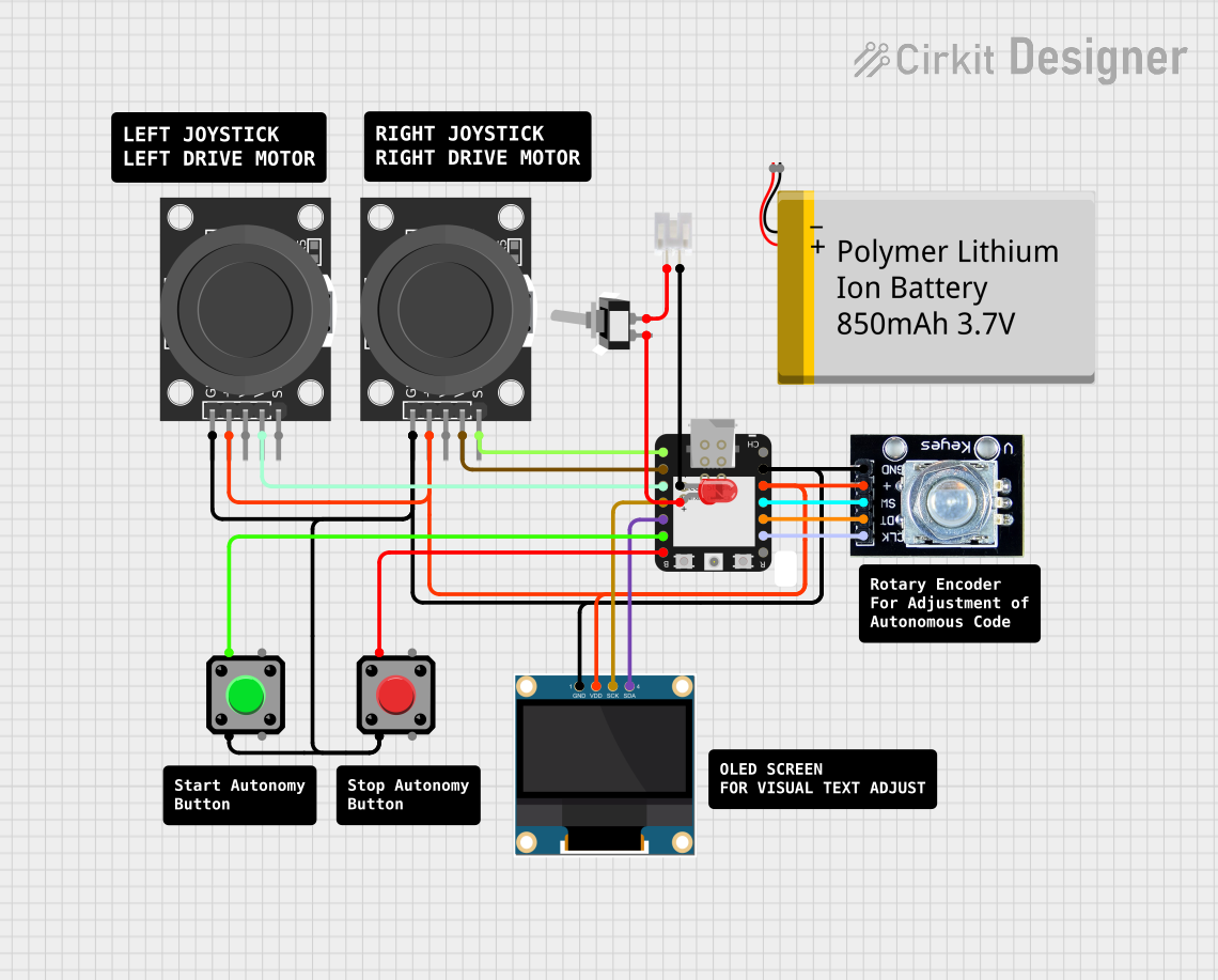
This document provides a detailed overview of a circuit designed to interface an ESP32-C3 microcontroller with various input and output devices. The circuit includes a joystick module, a rotary encoder, an OLED display, pushbuttons, a battery, a toggle switch, a JST connector, and an LED. The ESP32-C3 serves as the central processing unit, handling inputs from the joystick and rotary encoder, driving the OLED display, and managing the state of the LED through a toggle switch.
Component List
ESP32-C3
- Microcontroller with multiple GPIOs, I2C, UART, and power pins.
- Used as the main processing unit of the circuit.
Polymer Lithium Ion Battery - 850mAh
- Provides power to the circuit.
KY-023 Dual Axis Joystick Module (x2)
- Provides analog input from the joystick's two axes and a digital input from the joystick's button.
Rotary Encoder
- Provides incremental input from the rotation and a digital input from the built-in switch.
0.96" OLED
- A small display to provide visual output.
Pushbutton (x2)
- Provides digital input when pressed.
JST PH 2.0 connector
- Used for making a detachable power connection.
Toggle Switch SPST
- Single Pole Single Throw switch, used to control the power flow to the LED.
LED: Two Pin (red)
- Used as a visual indicator, controlled by the toggle switch.
Wiring Details
ESP32-C3
- GPIO2 / A0: Connected to the SW pin of the first KY-023 Joystick Module.
- GPIO3 / A1: Connected to the VRy pin of the first KY-023 Joystick Module.
- GPIO4 / A2: Connected to the VRy pin of the second KY-023 Joystick Module.
- GPIO5 / A3: Connected to the SCK pin of the 0.96" OLED.
- GPIO6 / SDA: Connected to the SDA pin of the 0.96" OLED.
- GPIO7 / SCL: Connected to Pin 1 of the first Pushbutton.
- GPIO21 / TX: Connected to Pin 1 of the second Pushbutton.
- GPIO8 / SCK: Connected to the clk pin of the Rotary Encoder.
- GPIO9 / MISO: Connected to the dt pin of the Rotary Encoder.
- GPIO10 / MOSI: Connected to the sw pin of the Rotary Encoder.
- 3.3V: Connected to the +5V pins of both KY-023 Joystick Modules, VDD of the 0.96" OLED, and + pin of the Rotary Encoder.
- GND: Common ground for all components.
Polymer Lithium Ion Battery - 850mAh
- VCC: Not directly connected in the provided net list.
- GND: Not directly connected in the provided net list.
KY-023 Dual Axis Joystick Module (x2)
- SW: Connected to GPIO2 / A0 of the ESP32-C3 (first module).
- VRy: Connected to GPIO3 / A1 of the ESP32-C3 (first module), and GPIO4 / A2 of the ESP32-C3 (second module).
- +5V: Connected to the 3.3V pin of the ESP32-C3.
- GND: Common ground with other components.
Rotary Encoder
- clk: Connected to GPIO8 / SCK of the ESP32-C3.
- dt: Connected to GPIO9 / MISO of the ESP32-C3.
- sw: Connected to GPIO10 / MOSI of the ESP32-C3.
- +: Connected to the 3.3V pin of the ESP32-C3.
- gnd: Common ground with other components.
0.96" OLED
- SCK: Connected to GPIO5 / A3 of the ESP32-C3.
- SDA: Connected to GPIO6 / SDA of the ESP32-C3.
- VDD: Connected to the 3.3V pin of the ESP32-C3.
- GND: Common ground with other components.
Pushbutton (x2)
- Pin 1: Connected to GPIO7 / SCL of the ESP32-C3 (first pushbutton) and GPIO21 / TX of the ESP32-C3 (second pushbutton).
- Pin 2: Common ground with other components.
JST PH 2.0 connector
- Pin 1: Connected to the cathode of the LED.
- Pin 2: Connected to the COM pin of the Toggle Switch SPST.
Toggle Switch SPST
- L1: Connected to the anode of the LED.
- COM: Connected to Pin 2 of the JST PH 2.0 connector.
LED: Two Pin (red)
- cathode: Connected to Pin 1 of the JST PH 2.0 connector.
- anode: Connected to the L1 pin of the Toggle Switch SPST.
Documented Code
No code has been provided for the microcontroller. The documentation of the code would include descriptions of the functionality, setup, and loop routines, along with any functions or libraries used to interface with the hardware components. Since no code is available, this section cannot be completed.