
Arduino Mega 2560 Controlled Robotic Vehicle with Bluetooth, IR, and Ultrasonic Sensors
View and Edit Project In Cirkit Designer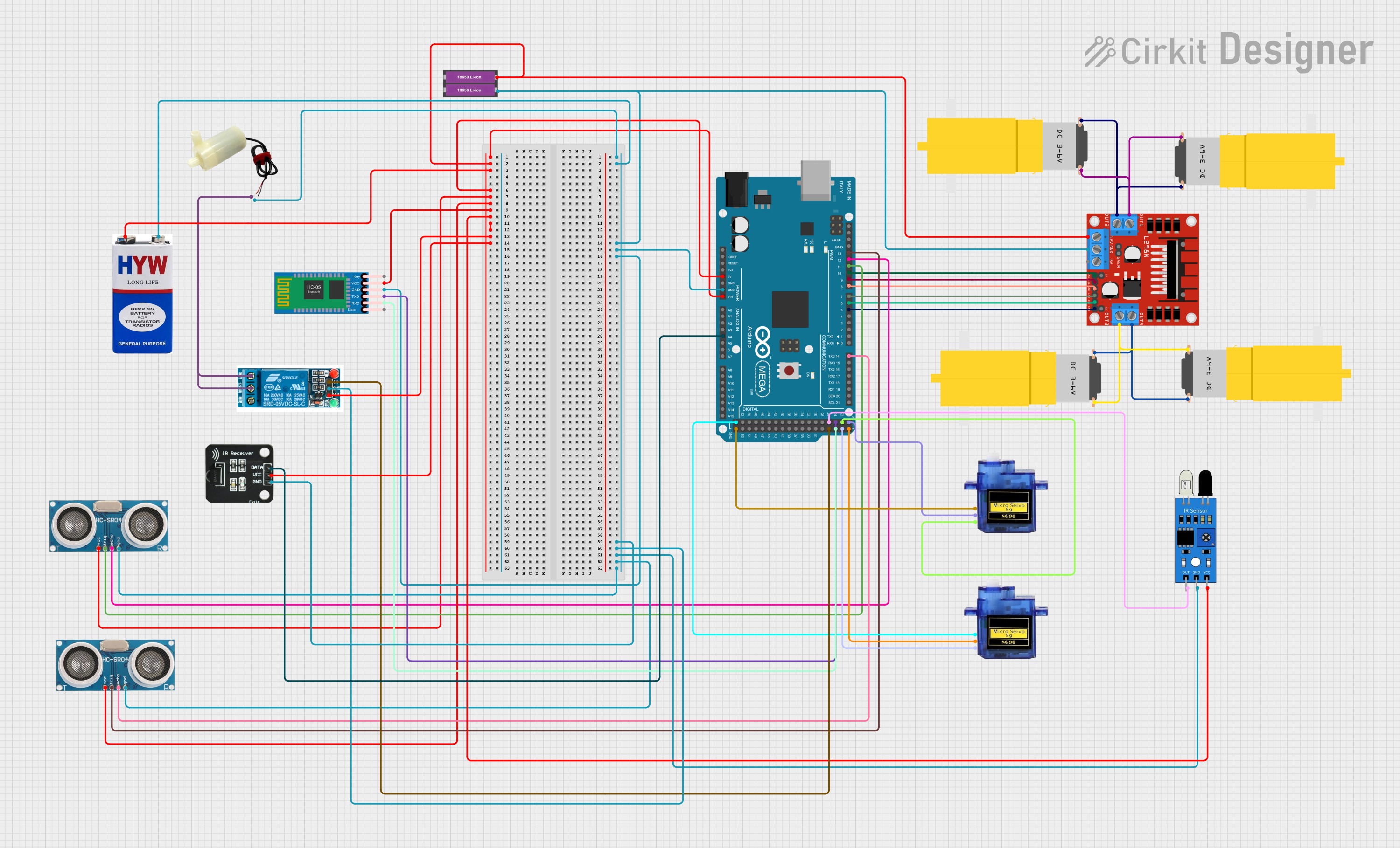
Circuit Documentation
Summary
This circuit integrates various components including an Arduino Mega 2560, L298N DC motor driver, IR sensor, ultrasonic sensors, IR receiver, DC motors, HC-05 Bluetooth module, a 9V battery, 18650 Li-ion batteries, a 5V mini water pump, micro servos, and a 5V relay. The circuit is designed to control motors, receive sensor inputs, and communicate via Bluetooth. Power is supplied by the 18650 Li-ion batteries and a 9V battery, with voltage regulation provided by the Arduino Mega 2560 and the L298N motor driver.
Component List
- Arduino Mega 2560: A microcontroller board based on the ATmega2560, with numerous digital and analog I/O pins.
- L298N DC Motor Driver: A module for controlling up to two DC motors, with direction and speed control.
- IR Sensor: A module for detecting obstacles or receiving IR signals.
- 18650 Li-ion Battery x 2: A power source for the circuit.
- Ultrasonic Sensor: A sensor for measuring distance via ultrasonic waves.
- IR Receiver: A component for receiving IR signals.
- DC Motors (Hobby Motor Gearmotor): Motors used for movement or other mechanical actions.
- HC-05 Bluetooth Module: A Bluetooth module for wireless communication.
- 9V Battery: An additional power source for the circuit.
- 5V Mini Water Pump: A pump for moving water.
- Micro Servo 9G: A small servo motor for precise control of movement.
- 5V Relay: An electromechanical switch used for controlling high power devices.
Wiring Details
Arduino Mega 2560
- VIN connected to 18650 Li-ion Battery x 2 (+) and L298N DC motor driver (12V)
- GND connected to various GND pins of other components
- 5V output connected to several components requiring 5V
- A4 connected to IR Receiver (DATA)
- D14/TX3 connected to Ultrasonic Sensor (Echo)
- D5 PWM connected to L298N DC motor driver (ENB)
- D6 PWM connected to L298N DC motor driver (IN4)
- D7 PWM connected to L298N DC motor driver (IN3)
- D8 PWM connected to L298N DC motor driver (IN2)
- D9 PWM connected to L298N DC motor driver (IN1)
- D10 PWM connected to L298N DC motor driver (ENA)
- D11 PWM connected to Ultrasonic Sensor (Trigger)
- D12 PWM connected to Ultrasonic Sensor (Echo)
- D13 PWM connected to Ultrasonic Sensor (Trigger)
- D22 connected to Micro Servo 9G (PWM)
- D23 connected to Micro Servo 9G (PWM)
- D24 connected to HC-05 Bluetooth Module (TXD)
- D25 connected to HC-05 Bluetooth Module (RXD)
- D26 connected to IR Sensor (out)
- D27 connected to 5V Relay (In)
L298N DC Motor Driver
- OUT1/OUT2 connected to DC Motors
- OUT3/OUT4 connected to DC Motors
- ENA/ENB connected to Arduino Mega 2560 for speed control
- IN1/IN2/IN3/IN4 connected to Arduino Mega 2560 for direction control
IR Sensor
- VCC and GND connected to power and ground respectively
- Out connected to Arduino Mega 2560 (D26)
Ultrasonic Sensors
- VCC and GND connected to power and ground respectively
- Trigger and Echo connected to Arduino Mega 2560 for distance measurement
IR Receiver
- VCC and GND connected to power and ground respectively
- DATA connected to Arduino Mega 2560 (A4)
HC-05 Bluetooth Module
- VCC and GND connected to power and ground respectively
- TXD/RXD connected to Arduino Mega 2560 for serial communication
5V Relay
- VCC and GND connected to power and ground respectively
- In connected to Arduino Mega 2560 (D27)
- Normally Open and Common terminal connected to 5V Mini Water Pump
Micro Servo 9G
- GND and +5V connected to power and ground respectively
- PWM connected to Arduino Mega 2560 for control signals
DC Motors (Hobby Motor Gearmotor)
- VCC and GND connected to L298N DC motor driver outputs
5V Mini Water Pump
- Positive pin connected to 5V Relay (Normally Open and Common terminal)
- Negative pin connected to ground
Documented Code
Arduino Mega 2560 Code (sketch.ino)
void setup() {
  // put your setup code here, to run once:

}

void loop() {
  // put your main code here, to run repeatedly:

}
Note: The provided code is a template and does not contain any functional code. It needs to be populated with the logic to control the components as per the circuit's requirements.