
Arduino UNO Bluetooth-Controlled Mecanum Wheels Robot with L298N Motor Drivers
View and Edit Project In Cirkit Designer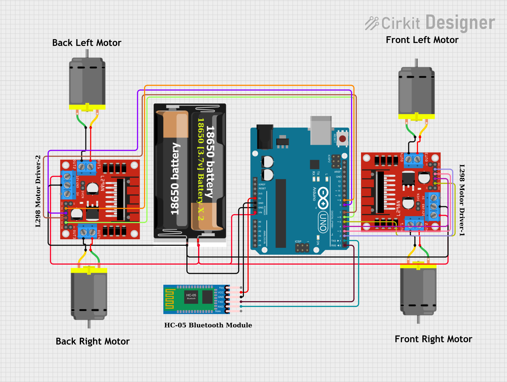
Circuit Documentation
Summary
This circuit is designed to control a Mecanum wheels robot using an Arduino UNO microcontroller. The robot is powered by two 18650 batteries and can be controlled via Bluetooth using an HC-05 Bluetooth module. The movement of the robot is managed by two L298N DC motor drivers, each controlling two DC motors.
Component List
2x 18650 Battery Pack
- Pins: VCC, GND
- Description: Provides power to the circuit.
Arduino UNO
- Pins: UNUSED, IOREF, Reset, 3.3V, 5V, GND, Vin, A0, A1, A2, A3, A4, A5, SCL, SDA, AREF, D13, D12, D11, D10, D9, D8, D7, D6, D5, D4, D3, D2, D1, D0
- Description: Microcontroller used to control the robot.
L298N DC Motor Driver (2 units)
- Pins: OUT1, OUT2, 12V, GND, 5V, OUT3, OUT4, 5V-ENA-JMP-I, 5V-ENA-JMP-O, +5V-J1, +5V-J2, ENA, IN1, IN2, IN3, IN4, ENB
- Description: Motor driver used to control the DC motors.
DC Motor (4 units)
- Pins: pin 1, pin 2
- Description: Motors used to drive the robot.
HC-05 Bluetooth Module
- Pins: Key, VCC, GND, TXD, RXD, State
- Description: Bluetooth module used for wireless communication.
Comment (8 units)
- Pins: None
- Description: Placeholder for comments in the circuit design.
Wiring Details
2x 18650 Battery Pack
VCC connected to:
- L298N DC motor driver (12V)
- Arduino UNO (Vin)
- L298N DC motor driver (12V)
GND connected to:
- L298N DC motor driver (GND)
- Arduino UNO (GND)
- L298N DC motor driver (GND)
Arduino UNO
Vin connected to:
- 2x 18650 Battery Pack (VCC)
- L298N DC motor driver (12V)
- L298N DC motor driver (12V)
GND connected to:
- 2x 18650 Battery Pack (GND)
- L298N DC motor driver (GND)
- L298N DC motor driver (GND)
- HC-05 Bluetooth Module (GND)
5V connected to:
- HC-05 Bluetooth Module (VCC)
D9 connected to:
- L298N DC motor driver (IN1)
D8 connected to:
- L298N DC motor driver (IN2)
D7 connected to:
- L298N DC motor driver (IN3)
D6 connected to:
- L298N DC motor driver (IN4)
D5 connected to:
- L298N DC motor driver (IN1)
D4 connected to:
- L298N DC motor driver (IN2)
D3 connected to:
- L298N DC motor driver (IN3)
D2 connected to:
- L298N DC motor driver (IN4)
D1 connected to:
- HC-05 Bluetooth Module (RXD)
D0 connected to:
- HC-05 Bluetooth Module (TXD)
L298N DC Motor Driver (1st Unit)
12V connected to:
- 2x 18650 Battery Pack (VCC)
- Arduino UNO (Vin)
- L298N DC motor driver (12V)
GND connected to:
- 2x 18650 Battery Pack (GND)
- Arduino UNO (GND)
- L298N DC motor driver (GND)
IN1 connected to:
- Arduino UNO (D9)
IN2 connected to:
- Arduino UNO (D8)
IN3 connected to:
- Arduino UNO (D7)
IN4 connected to:
- Arduino UNO (D6)
OUT1 connected to:
- DC Motor (pin 2)
OUT2 connected to:
- DC Motor (pin 1)
OUT3 connected to:
- DC Motor (pin 2)
OUT4 connected to:
- DC Motor (pin 1)
L298N DC Motor Driver (2nd Unit)
12V connected to:
- 2x 18650 Battery Pack (VCC)
- Arduino UNO (Vin)
- L298N DC motor driver (12V)
GND connected to:
- 2x 18650 Battery Pack (GND)
- Arduino UNO (GND)
- L298N DC motor driver (GND)
IN1 connected to:
- Arduino UNO (D5)
IN2 connected to:
- Arduino UNO (D4)
IN3 connected to:
- Arduino UNO (D3)
IN4 connected to:
- Arduino UNO (D2)
OUT1 connected to:
- DC Motor (pin 2)
OUT2 connected to:
- DC Motor (pin 1)
OUT3 connected to:
- DC Motor (pin 2)
OUT4 connected to:
- DC Motor (pin 1)
DC Motor (4 units)
pin 1 connected to:
- L298N DC motor driver (OUT2)
- L298N DC motor driver (OUT4)
- L298N DC motor driver (OUT2)
- L298N DC motor driver (OUT4)
pin 2 connected to:
- L298N DC motor driver (OUT1)
- L298N DC motor driver (OUT3)
- L298N DC motor driver (OUT1)
- L298N DC motor driver (OUT3)
HC-05 Bluetooth Module
VCC connected to:
- Arduino UNO (5V)
GND connected to:
- Arduino UNO (GND)
TXD connected to:
- Arduino UNO (D0)
RXD connected to:
- Arduino UNO (D1)
Code Documentation
//MECANUM WHEELS ROBOT

#define IN_11  2        // L298N #1 in 4 motor Front Right
#define IN_12  3        // L298N #1 in 3 motor Front Right
#define IN_13  4        // L298N #1 in 2 motor Front Left
#define IN_14  5        // L298N #1 in 1 motor Front Left

#define IN_21  6        // L298N #2 in 4 motor Back Left
#define IN_22  7       // L298N #2 in 3 motor Back Left
#define IN_23  8       // L298N #2 in 2 motor Back Right
#define IN_24  9      // L298N #2 in 1 motor Back Right

int command;             //Int to store app command state.
boolean state = 1;

void stopRobot() {
  digitalWrite(IN_11, LOW);
  digitalWrite(IN_12, LOW);

  digitalWrite(IN_13, LOW);
  digitalWrite(IN_14, LOW);

  digitalWrite(IN_24, LOW);
  digitalWrite(IN_23, LOW);

  digitalWrite(IN_22, LOW);
  digitalWrite(IN_21, LOW);
}

void back() {
  digitalWrite(IN_11, LOW);
  digitalWrite(IN_12, HIGH);

  digitalWrite(IN_13, LOW);
  digitalWrite(IN_14, HIGH);

  digitalWrite(IN_24, HIGH);
  digitalWrite(IN_23, LOW);

  digitalWrite(IN_22, HIGH);
  digitalWrite(IN_21, LOW);
}

void forward () {
  digitalWrite(IN_11, HIGH);
  digitalWrite(IN_12, LOW);

  digitalWrite(IN_13, HIGH);
  digitalWrite(IN_14, LOW);

  digitalWrite(IN_24, LOW);
  digitalWrite(IN_23, HIGH);

  digitalWrite(IN_22, LOW);
  digitalWrite(IN_21, HIGH);
}

void left() {
  digitalWrite(IN_11, HIGH);
  digitalWrite(IN_12, LOW);

  digitalWrite(IN_13, LOW);
  digitalWrite(IN_14, HIGH);

  digitalWrite(IN_24, LOW);
  digitalWrite(IN_23, HIGH);

  digital