ESP32-Based Wi-Fi Controlled Display with Rotary Encoder and Push Button
Circuit Documentation
Summary
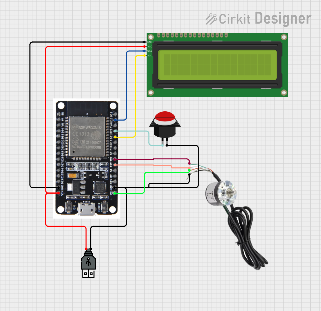
This document provides a detailed overview of a circuit that includes an ESP32 microcontroller, a 16x2 I2C LCD, an encoder, a push button, and a USB power source. The circuit is designed to interface these components for various functionalities, including display, input, and power management.
Component List
ESP32
- Description: A powerful microcontroller with built-in Wi-Fi and Bluetooth capabilities.
- Pins: EN, VP, VN, D34, D35, D32, D33, D25, D26, D27, D14, D12, D13, GND, VIN, 3V3, D15, D2, D4, RX2, TX2, D5, D18, D19, D21, RX0, TX0, D22, D23, BOOT
16x2 I2C LCD
- Description: A 16x2 character LCD display with I2C interface.
- Pins: GND, VCC, SDA, SCL
Encoder
- Description: A rotary encoder for input.
- Pins: Phase A, VCC, Phase B, GND
Push Button Round
- Description: A simple push button for user input.
- Pins: leg0, leg1
USB Power
- Description: A USB power source for providing power to the circuit.
- Pins: +, -
Wiring Details
ESP32
GND is connected to:
- GND of 16x2 I2C LCD
- leg1 of Push Button Round
- of USB Power
- GND of Encoder
VIN is connected to:
- VCC of 16x2 I2C LCD
- of USB Power
3V3 is connected to:
- VCC of Encoder
RX2 is connected to:
- Phase B of Encoder
TX2 is connected to:
- Phase A of Encoder
D21 is connected to:
- SCL of 16x2 I2C LCD
RX0 is connected to:
- leg0 of Push Button Round
D22 is connected to:
- SDA of 16x2 I2C LCD
16x2 I2C LCD
GND is connected to:
- GND of ESP32
VCC is connected to:
- VIN of ESP32
- of USB Power
SDA is connected to:
- D22 of ESP32
SCL is connected to:
- D21 of ESP32
Encoder
Phase A is connected to:
- TX2 of ESP32
VCC is connected to:
- 3V3 of ESP32
Phase B is connected to:
- RX2 of ESP32
GND is connected to:
- GND of ESP32
- of USB Power
- leg1 of Push Button Round
Push Button Round
leg0 is connected to:
- RX0 of ESP32
leg1 is connected to:
- GND of ESP32
- of USB Power
- GND of Encoder
USB Power
+ is connected to:
- VIN of ESP32
- VCC of 16x2 I2C LCD
- is connected to:
- GND of ESP32
- leg1 of Push Button Round
- GND of Encoder
Code
There is no code provided for the microcontrollers in this circuit.
This document provides a comprehensive overview of the circuit, including a summary, component list, wiring details, and code documentation. The wiring details ensure that each component is correctly connected to the ESP32 microcontroller and other components in the circuit.