
Arduino UNO-Based Gas and Flame Detection System with LCD Display and Bluetooth Alert
View and Edit Project In Cirkit Designer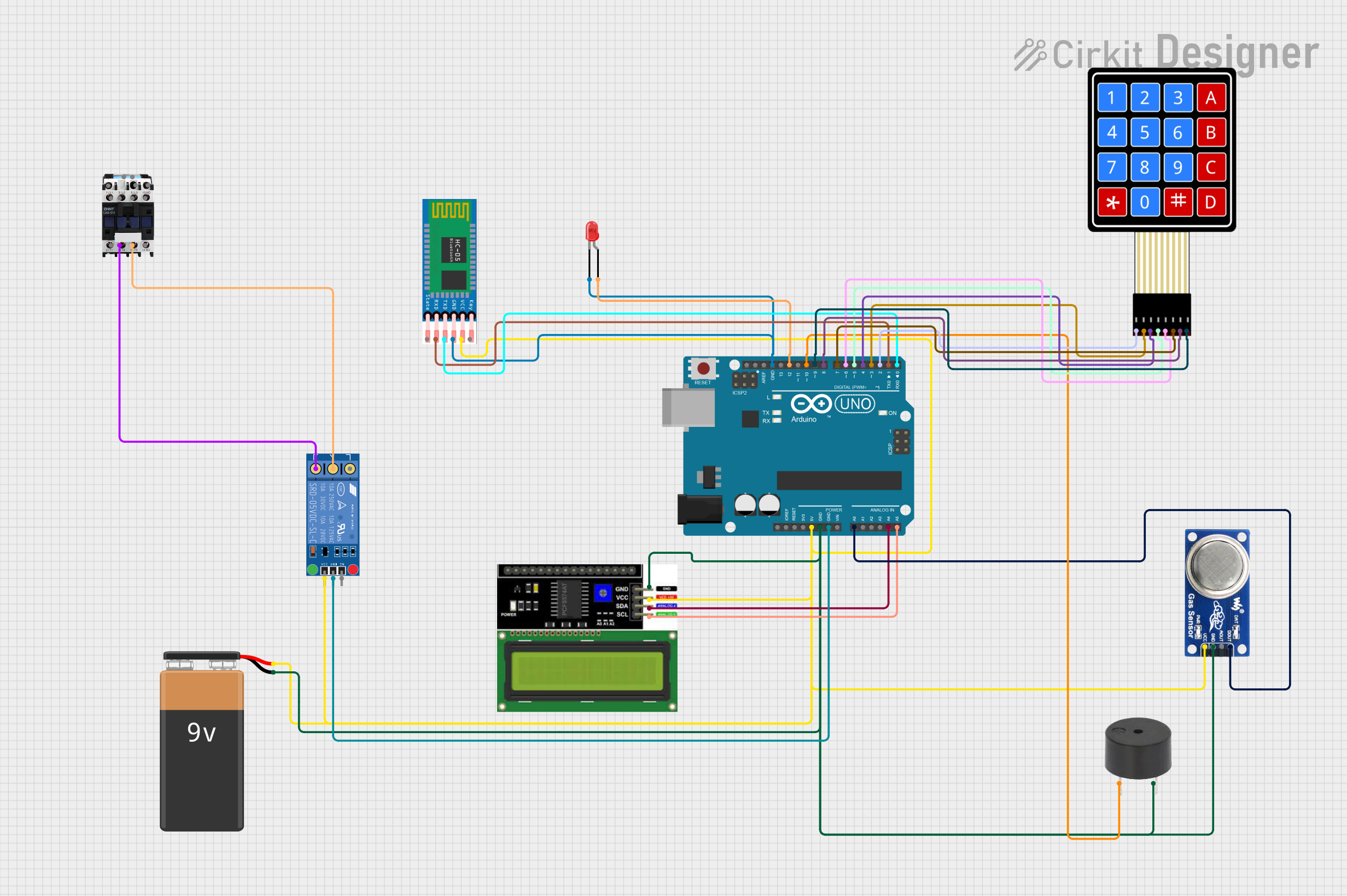
Circuit Documentation
Summary
The circuit in question is designed to monitor environmental conditions, specifically gas presence and flames, and to respond accordingly. It utilizes an Arduino UNO as the central microcontroller to interface with various sensors and output devices, including an MQ6 gas sensor, a flame sensor, an LCD I2C display, a buzzer, LEDs, a relay, and a Bluetooth module (HC-05). The circuit is powered by a 9V battery and includes a 4x4 membrane matrix keypad for user input. The system is designed to alert users to dangerous conditions by activating visual and auditory signals and to communicate alerts via Bluetooth.
Component List
- Arduino UNO: A microcontroller board based on the ATmega328P, featuring digital and analog I/O pins.
- LCD I2C Display: A liquid crystal display with an I2C interface for displaying text and numbers.
- Buzzer: An electronic component that emits sound when voltage is applied.
- LED (Red): A two-pin light-emitting diode that emits red light.
- HC-05: A Bluetooth module for wireless communication.
- KF-301 Relay: An electromechanical switch used to control high power devices.
- MQ6: A gas sensor for detecting LPG, butane, propane, methane, alcohol, hydrogen, and smoke.
- 9V Battery: A standard battery providing the power supply for the circuit.
- 4x4 Membrane Matrix Keypad: A keypad with 16 buttons arranged in a 4x4 matrix for user input.
- Magnetic Contactor: An electrically controlled switch used for switching a power circuit.
Wiring Details
Arduino UNO
- 5V: Connected to VCC of MQ6, LCD I2C Display, HC-05, KF-301 Relay.
- GND: Connected to GND of MQ6, LCD I2C Display, Buzzer, LED, HC-05, KF-301 Relay.
- A0: Connected to DO of MQ6.
- A4 (SDA): Connected to SDA of LCD I2C Display.
- A5 (SCL): Connected to SCL of LCD I2C Display.
- D0-D9: Connected to various pins of the 4x4 Membrane Matrix Keypad and HC-05.
- D10: Connected to PIN of Buzzer.
- D12: Connected to anode of LED.
LCD I2C Display
- GND: Connected to GND of 9V Battery.
- VCC: Connected to 5V of Arduino UNO.
- SDA: Connected to A4 of Arduino UNO.
- SCL: Connected to A5 of Arduino UNO.
Buzzer
- PIN: Connected to D10 of Arduino UNO.
- GND: Connected to GND of Arduino UNO.
LED (Red)
- Cathode: Connected to GND of Arduino UNO.
- Anode: Connected to D12 of Arduino UNO.
HC-05
- EN: Not connected.
- VCC: Connected to 5V of Arduino UNO.
- GND: Connected to GND of Arduino UNO.
- TXD: Connected to D0 of Arduino UNO.
- RXD: Connected to D1 of Arduino UNO.
- STATE: Not connected.
KF-301 Relay
- Signal: Not specified in the net list.
- Power: Connected to 5V of Arduino UNO.
- Ground: Connected to GND of Arduino UNO.
- NC: Connected to 4/T2 of Magnetic Contactor.
- C: Connected to 6/T3 of Magnetic Contactor.
- NO: Not specified in the net list.
MQ6
- VCC: Connected to 5V of Arduino UNO.
- GND: Connected to GND of Arduino UNO.
- A0: Not connected.
- DO: Connected to A0 of Arduino UNO.
9V Battery
- (+): Connected to VCC of MQ6, LCD I2C Display, KF-301 Relay, HC-05, Arduino UNO.
- (-): Connected to GND of MQ6, LCD I2C Display, Buzzer, LED, HC-05, KF-301 Relay, Arduino UNO.
4x4 Membrane Matrix Keypad
- R1-R4 and C1-C4: Connected to D2-D9 of Arduino UNO respectively.
Magnetic Contactor
- 4/T2: Connected to NC of KF-301 Relay.
- 6/T3: Connected to C of KF-301 Relay.
- Other pins: Not specified in the net list.
Documented Code
#include <Servo.h>
#include <SoftwareSerial.h>
#include <LiquidCrystal_I2C.h>  // Include the LiquidCrystal_I2C library

// Define sensor and control pins
const int mq2Pin = A0;        // MQ-2 sensor connected to analog pin A0
const int flameSensorPin = 4; // Flame sensor connected to digital pin 4
const int led1Pin = 5;        // First LED connected to digital pin 5 (SAFE indicator)
const int led2Pin = 6;        // Second LED connected to digital pin 6
const int led3Pin = 7;        // Third LED connected to digital pin 7
const int buzzerPin = 8;      // Buzzer connected to digital pin 8
const int servoPin = 9;       // Servo connected to digital pin 9
const int relayPin = 10;      // Relay module connected to digital pin 10
const int threshold = 300;    // Threshold for gas concentration

// Create Servo, SoftwareSerial, and LCD objects
Servo myServo;
SoftwareSerial hc05(2, 3);  // RX, TX
LiquidCrystal_I2C lcd(0x27, 16, 2); // LCD address 0x27, 16 columns, 2 rows

void setup() {
  // Set sensor and control pin modes
  pinMode(mq2Pin, INPUT);
  pinMode(flameSensorPin, INPUT);
  pinMode(led1Pin, OUTPUT);
  pinMode(led2Pin, OUTPUT);
  pinMode(led3Pin, OUTPUT);
  pinMode(buzzerPin, OUTPUT);
  pinMode(relayPin, OUTPUT);

  // Initialize the servo
  myServo.attach(servoPin);
  myServo.write(0);  // Set the servo to initial position

  // Start with relay, LEDs, and buzzer off
  digitalWrite(relayPin, LOW);      // Relay off initially
  digitalWrite(led1Pin, HIGH);      // LED1 on to indicate SAFE state
  digitalWrite(led2Pin, LOW);       // LED2 off
  digitalWrite(led3Pin, LOW);       // LED3 off
  digitalWrite(buzzerPin, LOW);     // Buzzer off

  // Initialize serial communication for debugging and Bluetooth
  Serial.begin(9600);
  hc05.begin(9600); // Initialize HC-05 Bluetooth communication

  // Initialize LCD
  lcd.begin(16,2);  // Initialize the LCD
  lcd.backlight();  // Turn on the LCD backlight

  // Display initial message
  lcd.setCursor(0, 0);
  lcd.print("--TECH_TITANS--");
  lcd.setCursor(0, 1);
  lcd.print("----WELCOME----");
  delay(2000);  // Wait for sensor to warm up
  lcd.clear();  // Clear the screen
}

void loop() {
  // Read the analog value from the MQ-2 sensor
  int gasSensorValue = analogRead(mq2Pin);

  // Read the digital value from the flame sensor
  bool flameDetected = digitalRead(flameSensorPin) == LOW;  // LOW means flame detected for most flame sensors

  // Print the gas sensor value to the Serial Monitor (optional)
  Serial.print("Gas Sensor Value: ");
  Serial.println(gasSensorValue);

  // Determine the state and update components accordingly
  bool gasLeak = gasSensorValue > threshold;
  bool danger = gasLeak || flameDetected;
  bool safe = !danger;

  // Update outputs based on sensor readings
  digitalWrite(relayPin, danger ? LOW : HIGH);
  digitalWrite(led1Pin, safe ? HIGH : LOW); // LED1 on when safe

  // Turn on all LEDs when both gas leak and flame are detected
  if (gasLeak && flameDetected) {
    digitalWrite(led2Pin, HIGH);  // LED2 on
    digitalWrite(led3Pin, HIGH);  // LED3 on
    digitalWrite(led1Pin, HIGH);
  } else {
    digitalWrite(led2Pin, flameDetected ? HIGH : LOW);
    digitalWrite(led3Pin, gasLeak ? HIGH : LOW); // LED3 on when gas leak is detected
  }

  digitalWrite(buzzerPin, danger ? HIGH : LOW);

  // Increase the servo angle when danger is detected
  myServo.write(danger ? 180 : 0); // Move to 180 degrees when danger is detected

  // Update the LCD display
  lcd.setCursor(0, 0);
  lcd.print("--TECH  TITANS--");

  if (gasLeak && flameDetected) {
    lcd.setCursor(0, 1