Cirkit Designer
Your all-in-one circuit design IDE
Home /
Project Documentation
Arduino-Controlled Robotic Servo System with Dual-Voltage ESCs

Circuit Documentation
Summary of the Circuit
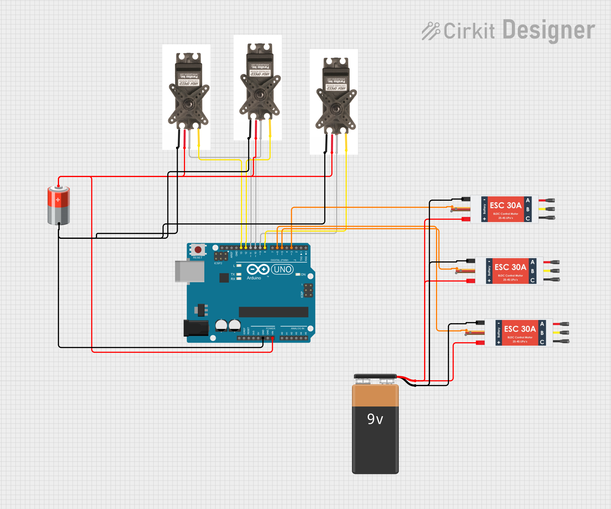
The circuit in question appears to be designed for controlling multiple servos and electronic speed controllers (ESCs) using an Arduino UNO microcontroller. The servos are likely used for precise positioning or feedback control, while the ESCs are typically used for controlling the speed of motors. The circuit includes a 5V battery to power the servos and a 9V battery to power the ESCs. The Arduino UNO is interfaced with the servos and ESCs through various digital pins for signal and feedback purposes.
Component List
FeedBack Servo
- Description: A servo motor with feedback capability.
- Pins: GND, V+, SIGNAL, FEEDBACK
Arduino UNO
- Description: A microcontroller board based on the ATmega328P.
- Pins: UNUSED, IOREF, Reset, 3.3V, 5V, GND, Vin, A0-A5, SCL, SDA, AREF, D0-D13
Electronic Speed Controller (ESC)
- Description: An electronic circuit that controls and regulates the speed of an electric motor.
- Pins: Battery VCC, Battery GND, Signal, 5v out, GND out, M1, M2, M3
5v Battery
- Description: A power source providing a 5V output.
- Pins: +, -
9V Battery
- Description: A power source providing a 9V output.
- Pins: +, -
Wiring Details
FeedBack Servo
- GND: Connected to the 5v Battery (-) and Arduino UNO GND.
- V+: Connected to the 5v Battery (+) and Arduino UNO Vin.
- SIGNAL: Connected to Arduino UNO Digital Pins (D9, D10, D11) for different servo instances.
- FEEDBACK: Connected to Arduino UNO Digital Pins (D8, D12, D13) for different servo instances.
Arduino UNO
- GND: Common ground with the 5v Battery and all servos.
- Vin: Connected to the 5v Battery (+).
- Digital Pins (D3, D5, D6, D8-D13): Used to interface with the servos and ESCs for signal and feedback.
Electronic Speed Controller (ESC)
- Battery VCC: Connected to the 9V Battery (+).
- Battery GND: Connected to the 9V Battery (-).
- Signal: Connected to Arduino UNO Digital Pins (D3, D5, D6) for different ESC instances.
5v Battery
- +: Powers the servos and Arduino UNO Vin.
- -: Common ground with the servos and Arduino UNO.
9V Battery
- +: Powers the ESCs.
- -: Common ground with the ESCs.
Documented Code
Arduino UNO Code (sketch.ino)
void setup() {
  // put your setup code here, to run once:

}

void loop() {
  // put your main code here, to run repeatedly:

}
Note: The provided code is a template and does not contain any specific logic for controlling the servos or ESCs. It will need to be populated with the appropriate setup and loop code to manage the connected devices.
Additional Files
- documentation.txt: This file is mentioned but no content was provided. It is likely intended for additional notes or manual documentation.