
Circuit Documentation
Summary
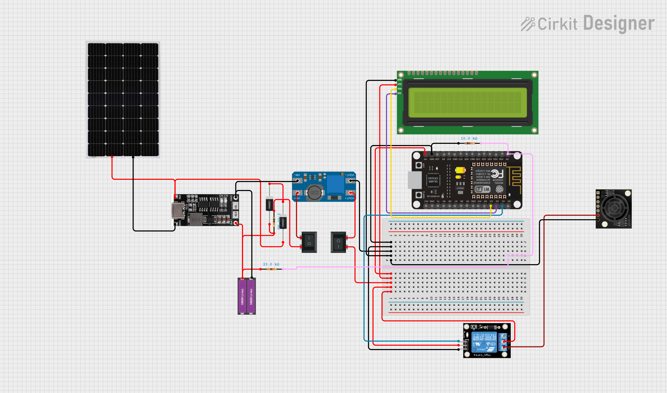
This circuit integrates various components including a microcontroller, display, relay module, sensors, switches, a solar panel, a battery charger, and power management modules. The primary controller is an ESP8266 NodeMCU which interfaces with an I2C LCD screen and controls a relay module. The system is powered by a solar panel charging circuit that charges a Li-ion battery, which in turn powers the circuit through a voltage booster (MT3608). The circuit also includes a Maxbotix ultrasonic sensor for distance measurement. Diodes and resistors are used for protection and voltage division respectively.
Component List
I2C LCD 16x2 Screen
A display module for showing information, interfaced with the ESP8266 NodeMCU via the I2C protocol.
Relay Module 1 Channel
An electromechanical switch controlled by the ESP8266 NodeMCU, used to control high power devices.
Solar Panel
A photovoltaic panel used to convert solar energy into electrical energy to charge the battery.
Rocker Switch (SPST)
A single-pole single-throw switch used to control the power flow in the circuit.
18650 Lithium Ion Charger
A charging module for 18650 Li-ion batteries, powered by the solar panel.
1N4007 Rectifier Diode
A diode used to prevent reverse current flow in the charging circuit.
Resistor
A passive two-terminal electrical component used to limit current or divide voltages in the circuit.
Maxbotix MaxSonar Ultrasonic Sensor (Hi-Res)
A sensor used to measure distance via ultrasonic waves, powered by the relay module.
MT3608
A DC-DC step-up converter used to boost the voltage to the required level for the ESP8266 NodeMCU and other components.
18650 Li-ion Battery x 2
A pair of rechargeable batteries providing power to the circuit.
ESP8266 NodeMCU
A microcontroller with Wi-Fi capability that controls the relay module, reads sensor data, and drives the I2C LCD screen.
Wiring Details
I2C LCD 16x2 Screen
- SCL: Connected to ESP8266 NodeMCU (D2)
- SDA: Connected to ESP8266 NodeMCU (D3)
- VCC (5V): Connected to ESP8266 NodeMCU (VIN)
- GND: Common ground with ESP8266 NodeMCU
Relay Module 1 Channel
- S: Controlled by ESP8266 NodeMCU (D1)
- 5V: Powered by ESP8266 NodeMCU (VIN)
- GND: Common ground with ESP8266 NodeMCU
- NO: Connected to Maxbotix Ultrasonic Sensor (+5V)
- COM: Connected to Rocker Switch (SPST)
Solar Panel
- +: Connected to 18650 Lithium Ion Charger (V IN) through a 1N4007 Rectifier Diode (Anode)
- -: Common ground with 18650 Lithium Ion Charger
Rocker Switch (SPST)
- 1: Connected to MT3608 (VOUT+)
- 2: Connected to Relay Module (COM) and another Rocker Switch (SPST)
18650 Lithium Ion Charger
- V IN: Connected to Solar Panel (+)
- GND: Common ground with Solar Panel
- BAT IN: Connected to 18650 Li-ion Battery (+) through a 1N4007 Rectifier Diode (Anode)
- BAT GND: Common ground with 18650 Li-ion Battery
1N4007 Rectifier Diode
- Anode: Connected to Solar Panel (+) and 18650 Lithium Ion Charger (V IN)
- Cathode: Connected to Rocker Switch (SPST)
Resistor
- Various resistors are used in the circuit for current limiting and voltage division.
Maxbotix MaxSonar Ultrasonic Sensor (Hi-Res)
- +5V: Powered by Relay Module (NO)
- GND: Common ground with ESP8266 NodeMCU
MT3608
- VIN+: Connected to Rocker Switch (SPST)
- VIN-: Common ground with 18650 Li-ion Battery
- VOUT+: Connected to Rocker Switch (SPST)
- VOUT-: Common ground with ESP8266 NodeMCU
18650 Li-ion Battery x 2
- +: Connected to 18650 Lithium Ion Charger (BAT IN) and various resistors
- -: Common ground with 18650 Lithium Ion Charger
ESP8266 NodeMCU
- VIN: Connected to I2C LCD Screen (VCC), Relay Module (5V), and Rocker Switch (SPST)
- GND: Common ground with various components
- D1: Controls Relay Module (S)
- D2: Connected to I2C LCD Screen (SCL)
- D3: Connected to I2C LCD Screen (SDA)
- A0: Connected to resistors for voltage division
Documented Code
No code was provided for the microcontroller. The documentation of the code would include details on how the ESP8266 NodeMCU is programmed to interface with the I2C LCD screen, control the relay module, and read data from the Maxbotix ultrasonic sensor. It would also include the setup of Wi-Fi connectivity and any web server or MQTT functionalities if implemented.