Cirkit Designer
Your all-in-one circuit design IDE
Home /
Project Documentation
Arduino UNO-Based Sensor Monitoring and Control System with ESP32-CAM and GSM

Circuit Documentation
Summary
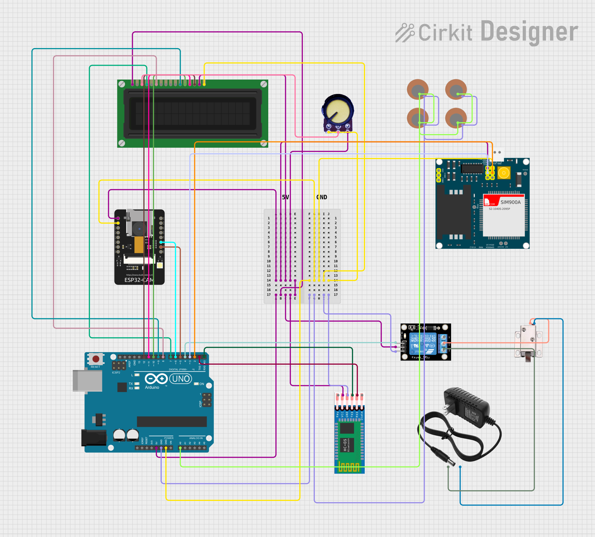
This document provides a detailed overview of a circuit that includes a variety of components such as an Arduino UNO, ESP32-CAM, relay module, solenoid lock, HC-05 Bluetooth module, potentiometer, LCD display, power supply, and SIM900A GSM module. The circuit is designed to interface with various sensors and modules to perform a range of functions, which could include wireless communication, display interfacing, and actuator control.
Component List
Arduino UNO
- Microcontroller board based on the ATmega328P
- It has 14 digital input/output pins, 6 analog inputs, a USB connection, a power jack, an ICSP header, and a reset button.
ESP32-CAM
- A small camera module with the ESP32-S chip that besides the camera also includes Wi-Fi and Bluetooth functionalities.
Relay Module (1 channel)
- An electrically operated switch that allows you to control a high power circuit with a low power signal.
12V Solenoid Lock
- An electromagnetic lock that is actuated by a 12V power supply to lock or unlock.
HC-05 Bluetooth Module
- A Bluetooth module for serial communication which operates as a master or slave.
Potentiometer
- A three-terminal resistor with a rotating contact that forms an adjustable voltage divider.
LCD Display (16 pin)
- A liquid crystal display that can show up to 16 characters per line and can have multiple lines.
12V Power Supply
- Provides a 12V voltage supply to power various components in the circuit.
SIM900A GSM Module
- A complete Dual-band GSM/GPRS module that can provide SMS and voice communication capabilities to embedded systems.
Piezo Sensors
- Sensors that generate a voltage when mechanical force is applied to them.
Wiring Details
Arduino UNO
- 5V: Connected to the 5V power bus.
- GND: Connected to the ground bus.
- A0: Connected to Piezo Sensors.
- D0-D12: Connected to various components for control and communication.
ESP32-CAM
- 5V: Connected to the 5V power bus.
- GND: Connected to the ground bus.
- VOR: Connected to Arduino UNO D6.
- VOT: Connected to Arduino UNO D5.
Relay Module (1 channel)
- S: Controlled by Arduino UNO D4.
- 5V: Connected to the 5V power bus.
- GND: Connected to the ground bus.
- COM: Connected to the 12V solenoid lock.
- NO: Connected to the 12V power supply.
12V Solenoid Lock
- VCC: Connected to the 12V power supply through the relay module.
- GND: Connected to the ground bus.
HC-05 Bluetooth Module
- VCC: Connected to the 5V power bus.
- GND: Connected to the ground bus.
- TXD: Connected to Arduino UNO D0.
- RXD: Connected to Arduino UNO D1.
Potentiometer
- VCC: Connected to the 5V power bus.
- GND: Connected to the ground bus.
- Output: Connected to the LCD Display VO pin.
LCD Display (16 pin)
- VSS: Connected to the 5V power bus.
- VDD: Connected to the 5V power bus.
- VO: Connected to the Potentiometer output.
- RS, E, DB4-DB7: Controlled by Arduino UNO D7-D12.
- A: Connected to the 5V power bus.
- K: Connected to the ground bus.
12V Power Supply
- +: Connected to the Relay Module NO and 12V solenoid lock VCC.
- -: Connected to the ground bus.
SIM900A GSM Module
- VCC: Connected to the 5V power bus.
- GND: Connected to the ground bus.
- 5VT: Connected to Arduino UNO D3.
- 5VR: Connected to Arduino UNO D2.
Piezo Sensors
- +: Connected to Arduino UNO A0.
- -: Connected to the ground bus.
Documented Code
Arduino UNO Code (sketch.ino)
void setup() {
  // put your setup code here, to run once:

}

void loop() {
  // put your main code here, to run repeatedly:

}
Additional Notes
- The code provided for the Arduino UNO is a template with empty setup and loop functions. Actual implementation code will be required to control and interact with the connected components.
- The HC-05 Bluetooth module and SIM900A GSM module require additional AT commands for proper initialization and operation, which are not included in this documentation.
- The LCD display requires initialization and a library to control the display functions, which are not provided in this documentation.
- The ESP32-CAM module may require separate programming and setup to function correctly with the Arduino UNO.
- The relay module should be used with caution, ensuring that the power ratings do not exceed the module's specifications.