Cirkit Designer
Your all-in-one circuit design IDE
Home /
Project Documentation
Arduino UNO Controlled Grove LED Bar Display
Circuit Documentation
Summary of the Circuit
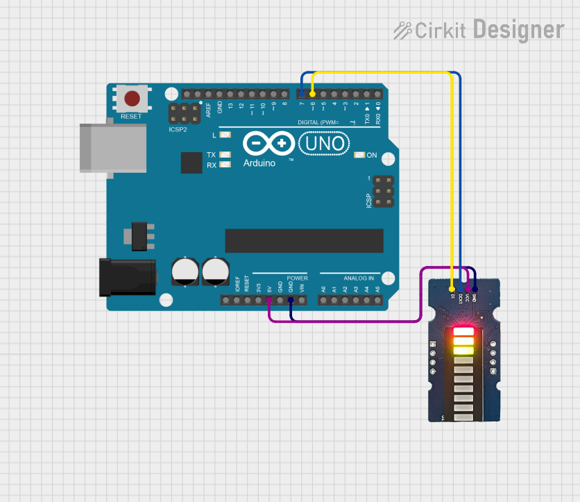
This circuit consists of an Arduino UNO microcontroller board interfaced with a Grove LED bar. The Arduino UNO is responsible for controlling the LED bar, which likely displays some form of visual output based on the program uploaded to the Arduino. The circuit is powered through the Arduino UNO's 5V and GND pins, and the LED bar is controlled via two digital pins on the Arduino.
Component List
Arduino UNO
- Description: A microcontroller board based on the ATmega328P.
- Pins: UNUSED, IOREF, Reset, 3.3V, 5V, GND, Vin, A0-A5, SCL, SDA, AREF, D0-D13.
- Purpose: Acts as the central processing unit of the circuit, running the embedded code to control the Grove LED bar.
Grove LED Bar
- Description: A 10-segment LED bar graph that can be set to various lighting patterns.
- Pins: gnd, vcc, DI, DCKI.
- Purpose: Provides a visual output that can be programmed via the Arduino UNO.
Wiring Details
Arduino UNO
- 5V connected to Grove LED bar's vcc pin.
- GND connected to Grove LED bar's gnd pin.
- D7 connected to Grove LED bar's DCKI pin.
- D6 connected to Grove LED bar's DI pin.
Grove LED Bar
- gnd connected to Arduino UNO's GND pin.
- vcc connected to Arduino UNO's 5V pin.
- DI connected to Arduino UNO's D6 pin.
- DCKI connected to Arduino UNO's D7 pin.
Documented Code
Arduino UNO Code (sketch.ino)
void setup() {
  // put your setup code here, to run once:

}

void loop() {
  // put your main code here, to run repeatedly:

}
Note: The provided code is a template and does not contain any specific instructions for controlling the Grove LED bar. The user should add the necessary code within the setup() and loop() functions to control the LED bar as desired.