
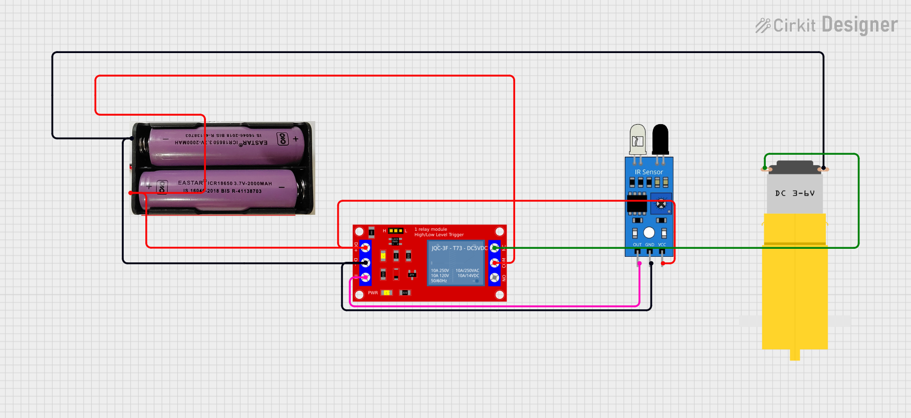
Circuit Documentation
Summary of the Circuit
The circuit described by the provided inputs consists of two IR sensors, two 1 Channel 5V Relay Modules, a 7.4V power source, and a motor. The IR sensors are used to detect objects or motion and trigger the relay modules. The relay modules control the power flow to the motor, which is powered by the 7.4V source. The circuit is designed to activate the motor when one of the IR sensors outputs a signal.
Component List
1 Channel 5V Relay Module
- Description: A relay module that can be used to control high power devices and appliances.
- Pins: VCC+, VCC- (GND), IN, N.O., COM, N.C.
IR Sensor
- Description: An infrared sensor capable of detecting object presence or motion.
- Pins: out, gnd, vcc
7.4V Power Source
- Description: A power source providing a voltage of 7.4V.
- Pins: +, -
Motor Amarillo Motorreductor Hobby
- Description: A hobby motor that operates on a voltage provided by the circuit.
- Pins: vcc, GND
Wiring Details
1 Channel 5V Relay Module
- VCC+: Connected to the 7.4V power source (+ pin) and the VCC pin of an IR sensor.
- VCC- (GND): Connected to the 7.4V power source (- pin), the GND pin of an IR sensor, and the VCC pin of the Motor Amarillo Motorreductor Hobby.
- IN: Connected to the out pin of an IR sensor.
- N.O.: Not connected in this circuit.
- COM: Connected to the VCC+ pin (shared with the 7.4V power source).
- N.C.: Connected to the GND pin of the Motor Amarillo Motorreductor Hobby.
IR Sensor
- out: Connected to the IN pin of a 1 Channel 5V Relay Module.
- gnd: Connected to the VCC- (GND) pin of a 1 Channel 5V Relay Module and the 7.4V power source (- pin).
- vcc: Connected to the VCC+ pin of a 1 Channel 5V Relay Module and the 7.4V power source (+ pin).
7.4V Power Source
- +: Connected to the VCC+ pin of a 1 Channel 5V Relay Module and the vcc pin of an IR sensor.
- -: Connected to the VCC- (GND) pin of a 1 Channel 5V Relay Module, the gnd pin of an IR sensor, and the VCC pin of the Motor Amarillo Motorreductor Hobby.
Motor Amarillo Motorreductor Hobby
- vcc: Connected to the VCC- (GND) pin of a 1 Channel 5V Relay Module and the 7.4V power source (- pin).
- GND: Connected to the N.C. pin of a 1 Channel 5V Relay Module.
Documented Code
No code has been provided for any microcontrollers in the circuit. If code becomes available, it should be documented in this section with appropriate comments and explanations for each function and routine.