Arduino Nano Controlled Gas Detection System with Servo Actuator and LCD Alert Display
Circuit Documentation
Summary
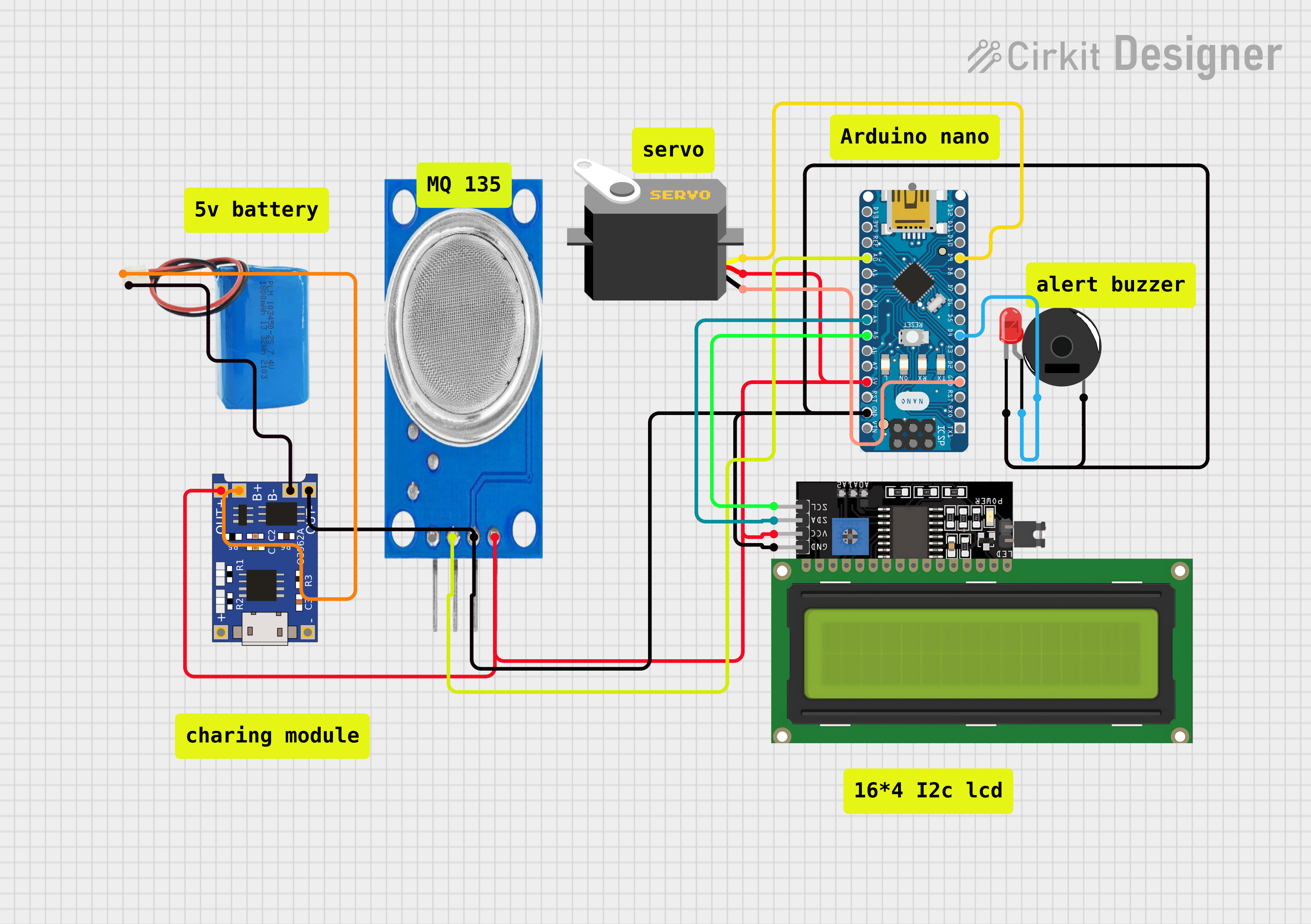
The circuit is designed to monitor gas levels using an MQ135 gas sensor and display the readings on an LCD display. If the gas level exceeds a certain threshold, a piezo buzzer is activated, and a servo motor is moved to a specific position as an alert mechanism. The system is controlled by an Arduino Nano microcontroller, which also manages the I2C communication with the LCD display. A TP4056 module is used for battery management, and a 5V battery provides the power supply.
Component List
Arduino Nano
- Microcontroller board based on the ATmega328P
- It has digital and analog I/O pins, and it is used as the central controller for the circuit.
Servo
- A motor that can be precisely controlled for angular position
- Used to perform a physical action when a certain gas level is detected.
MQ135 Gas Sensor
- A sensor for detecting a wide range of gases, including NH3, NOx, alcohol, benzene, smoke, and CO2.
- Used to monitor the gas levels in the environment.
Piezo Buzzer
- An electronic device that emits a tone when it is driven by an electrical signal.
- Used as an audible alert when a certain gas level is detected.
LED: Two Pin (red)
- A basic red light-emitting diode.
- Used as a visual indicator in the circuit.
LCD Display 16x4 I2C
- An alphanumeric liquid crystal display with an I2C interface.
- Used to display the gas level readings and alert messages.
TP4056
- A lithium battery charge management and protection module.
- Used for charging the battery and protecting the circuit from overcurrent conditions.
5v Battery
- A power source for the circuit.
- Provides the necessary voltage for the circuit operation.
Wiring Details
Arduino Nano
GNDconnected to the ground net, which includes the Servo (gnd), MQ135 (GND), Piezo Buzzer (pin 2), LED (cathode), LCD Display (GND), and TP4056 (OUT-).D4connected to the anode of the LED and pin 1 of the Piezo Buzzer.D9connected to the pulse pin of the Servo.5Vconnected to the power net, which includes the VCC of the Servo, MQ135 (VCC), and LCD Display (VCC).A5connected to the SCL pin of the LCD Display.A4connected to the SDA pin of the LCD Display.A0connected to the A0 pin of the MQ135 Gas Sensor.
Servo
gndconnected to the ground net.vccconnected to the power net.pulseconnected toD9on the Arduino Nano.
MQ135 Gas Sensor
GNDconnected to the ground net.VCCconnected to the power net.A0connected toA0on the Arduino Nano.
Piezo Buzzer
pin 1connected toD4on the Arduino Nano.pin 2connected to the ground net.
LED: Two Pin (red)
cathodeconnected to the ground net.anodeconnected toD4on the Arduino Nano.
LCD Display 16x4 I2C
GNDconnected to the ground net.VCCconnected to the power net.SCLconnected toA5on the Arduino Nano.SDAconnected toA4on the Arduino Nano.
TP4056
OUT-connected to the ground net.OUT+connected to the power net.B-connected to the negative pin of the 5v Battery.B+connected to the positive pin of the 5v Battery.
5v Battery
negativeconnected toB-on the TP4056.positiveconnected toB+on the TP4056.
Documented Code
#include <Servo.h>
#include <LiquidCrystal_I2C.h>

LiquidCrystal_I2C lcd(0x27,16,2);
const int gasSensorPin = A0;  // Analog pin connected to the MQ2 gas sensor
const int buzzer = 4;         // Digital pin connected to the buzzer
const int servoPin = 9;       // Digital pin connected to the servo
const int gasThreshold = 400; // Threshold value for gas detection (adjust based on your testing)

Servo myServo;  // Create servo object to control a servo
bool servoMoved = false; // Flag to check if the servo has already moved

void setup() {
  pinMode(gasSensorPin, INPUT);
  pinMode(buzzer, OUTPUT);
  myServo.attach(servoPin);
  myServo.write(0); // Initial position of the servo
  Serial.begin(9600); // Initialize serial communication for debugging
}

void loop() {
  int analogSensor = analogRead(gasSensorPin);
  int gasvalue = (analogSensor - 50) / 35;  // Gas module sensitivity

  lcd.setCursor(0,0);
  lcd.print("GAS Level:");
  lcd.setCursor(10,0);
  lcd.print(gasvalue);
  lcd.setCursor(12,0);
  lcd.print("%");

  // Checks if it has reached the threshold value
  if (gasvalue > gasThreshold && !servoMoved) { // Gas percentage alert
    digitalWrite(buzzer, HIGH); // Turn on the buzzer
    delay(2000); // Beep for 2 seconds
    digitalWrite(buzzer, LOW); // Turn off the buzzer

    myServo.write(75); // Rotate the servo to 90 degrees
    servoMoved = true; // Set the flag to indicate the servo has moved
    lcd.setCursor(0,1);
    lcd.print("DANGER");
    lcd.setCursor(1,1);
    lcd.print("auto reg off");
    tone(buzzer, 1000, 10000);
  } else {
    lcd.setCursor(0,1);
    lcd.print("NORMAL");
    noTone(buzzer);
  }
  delay(1000);
  lcd.clear();
}
This code is responsible for reading the gas level from the MQ135 sensor, displaying the value on the LCD, and triggering the buzzer and servo motor when the gas level exceeds the threshold. The LCD displays the current gas level percentage and shows a "DANGER" message along with turning off the regulator when the threshold is crossed. The servo moves to a 75-degree position as part of the alert mechanism.