
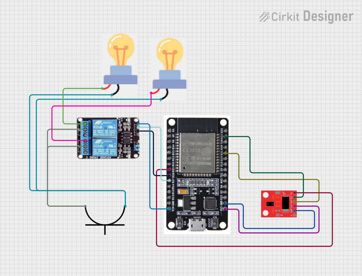
Circuit Documentation
Summary
This circuit utilizes an ESP32 microcontroller to control two appliances via a 2-channel relay module. The control is based on gestures detected by an APDS-9960 RGB and Gesture Sensor. The ESP32 reads gestures and accordingly switches the relays to turn the appliances (bulbs) on or off. The circuit is powered by an AC power plug.
Component List
ESP32
- Description: A powerful microcontroller with built-in Wi-Fi and Bluetooth capabilities.
- Pins: EN, VP, VN, D34, D35, D32, D33, D25, D26, D27, D14, D12, D13, GND, VIN, 3V3, D15, D2, D4, RX2, TX2, D5, D18, D19, D21, RX0, TX0, D22, D23, BOOT
APDS-9960 RGB and Gesture Sensor
- Description: A sensor capable of detecting RGB color and gestures.
- Pins: VL, GND, VCC, SDA, SCL, INT
2-channel Relay
- Description: A relay module with two channels for controlling high voltage appliances.
- Pins: NC, COM, NO, VCC, IN2, IN1, GND
Bulb (x2)
- Description: Standard light bulbs used as appliances in this circuit.
- Pins: GND, power
AC Power Plug
- Description: Provides AC power to the circuit.
- Pins: positive terminal, negative terminal
Wiring Details
ESP32
- D25 connected to INT of APDS-9960 RGB and Gesture Sensor
- D26 connected to IN1 of 2-channel Relay
- D27 connected to IN2 of 2-channel Relay
- VIN connected to VCC of 2-channel Relay
- 3V3 connected to VCC of APDS-9960 RGB and Gesture Sensor
- GND connected to GND of APDS-9960 RGB and Gesture Sensor
- D21 connected to SDA of APDS-9960 RGB and Gesture Sensor
- D22 connected to SCL of APDS-9960 RGB and Gesture Sensor
APDS-9960 RGB and Gesture Sensor
- INT connected to D25 of ESP32
- VCC connected to 3V3 of ESP32
- GND connected to GND of ESP32
- SDA connected to D21 of ESP32
- SCL connected to D22 of ESP32
2-channel Relay
- IN1 connected to D26 of ESP32
- IN2 connected to D27 of ESP32
- VCC connected to VIN of ESP32
- COM connected to positive terminal of AC Power Plug
- NO connected to power of Bulb 1
- NO connected to power of Bulb 2
Bulb 1
- power connected to NO of 2-channel Relay
- GND connected to negative terminal of AC Power Plug
Bulb 2
- power connected to NO of 2-channel Relay
- GND connected to negative terminal of AC Power Plug
AC Power Plug
- positive terminal connected to COM of 2-channel Relay
- negative terminal connected to GND of Bulb 1 and Bulb 2
Code Documentation
Code for ESP32
#include <Wire.h>
#include <Adafruit_APDS9960.h>

Adafruit_APDS9960 apds;
const int relay1 = 26;  // GPIO for Relay 1
const int relay2 = 27;  // GPIO for Relay 2

void setup() {
  Serial.begin(115200);
  pinMode(relay1, OUTPUT);
  pinMode(relay2, OUTPUT);

  digitalWrite(relay1, LOW); // Start with appliances off
  digitalWrite(relay2, LOW);

  if (!apds.begin()) {
    Serial.println("APDS9960 initialization failed!");
    while (1);
  }
  apds.enableGesture(true);
  Serial.println("APDS9960 ready!");
}

void loop() {
  if (apds.gestureAvailable()) {
    int gesture = apds.readGesture();
    switch (gesture) {
      case APDS9960_DOWN:
        Serial.println("Down Swipe - Appliance 2 OFF");
        digitalWrite(relay2, LOW);
        break;
      case APDS9960_UP:
        Serial.println("Up Swipe - Appliance 2 ON");
        digitalWrite(relay2, HIGH);
        break;
      case APDS9960_LEFT:
        Serial.println("Left Swipe - Appliance 1 OFF");
        digitalWrite(relay1, LOW);
        break;
      case APDS9960_RIGHT:
        Serial.println("Right Swipe - Appliance 1 ON");
        digitalWrite(relay1, HIGH);
        break;
      default:
        break;
    }
  }
}
This code initializes the APDS-9960 sensor and sets up the relays connected to the ESP32. It reads gestures and controls the relays to turn the appliances on or off based on the detected gestures.