
Arduino and ESP32-Based Smart Water Flow Monitoring System with I2C LCD Display
View and Edit Project In Cirkit Designer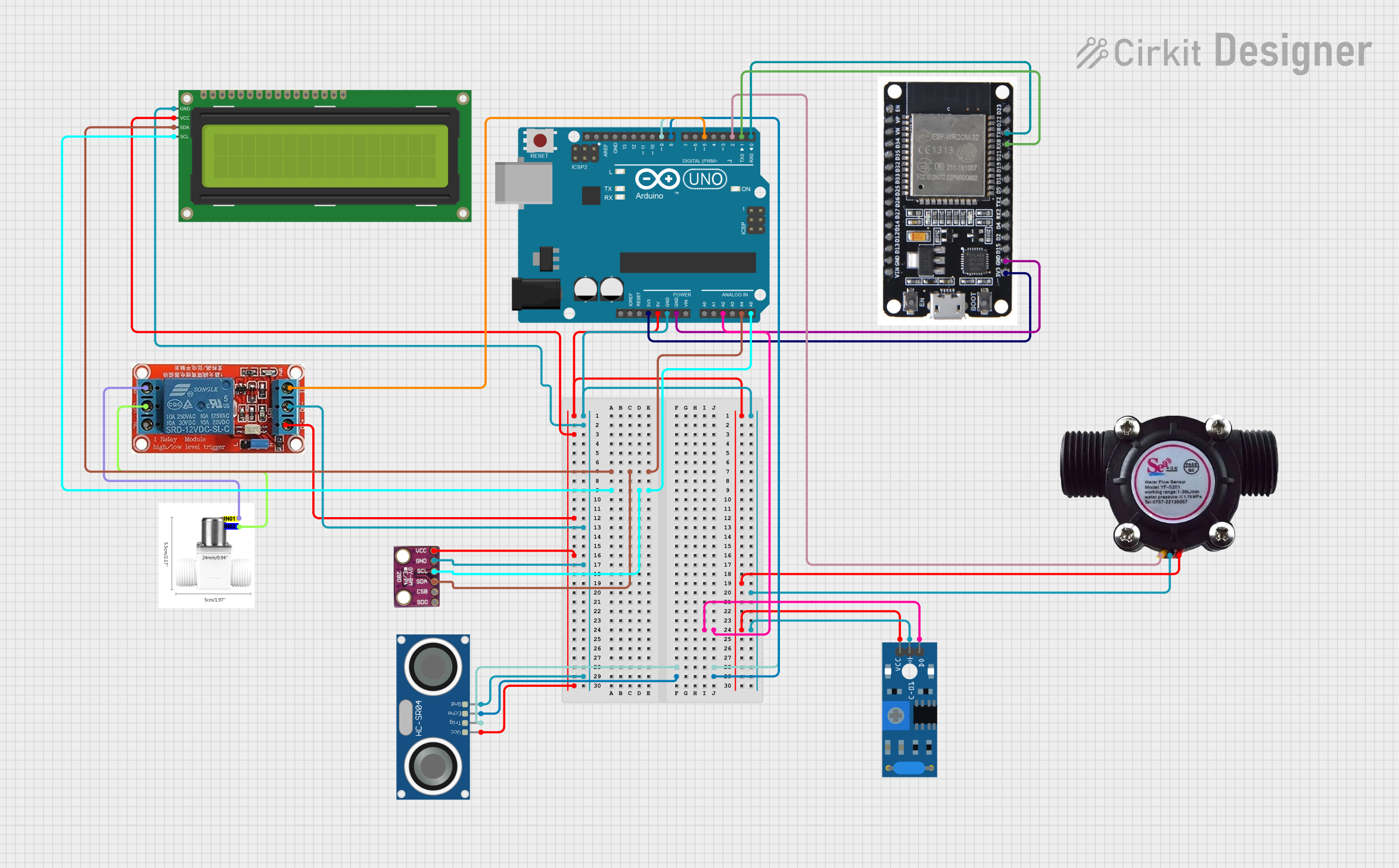
Circuit Documentation
Summary
This circuit involves an Arduino UNO microcontroller interfacing with various sensors and modules, including a BMP280 pressure sensor, an SW-420 vibration sensor, an HC-SR04 ultrasonic sensor, a water flow sensor, a 16x2 I2C LCD, an ESP32 microcontroller, a 12V relay, and a valve solenoid water. The circuit is designed to collect data from these sensors and display it on the LCD, with additional control functionalities provided by the relay and solenoid valve.
Component List
Arduino UNO
- Description: A microcontroller board based on the ATmega328P.
- Pins: UNUSED, IOREF, Reset, 3.3V, 5V, GND, Vin, A0, A1, A2, A3, A4, A5, SCL, SDA, AREF, D13, D12, D11, D10, D9, D8, D7, D6, D5, D4, D3, D2, D1, D0
BMP280
- Description: A digital pressure sensor.
- Pins: SDO, CSB, SDA, SCL, GND, VCC
SW-420 Vibration Sensor
- Description: A vibration sensor module.
- Pins: vcc, Ground, Digital output
HC-SR04 Ultrasonic Sensor
- Description: An ultrasonic distance sensor.
- Pins: VCC, TRIG, ECHO, GND
Water Flow Sensor
- Description: A sensor to measure the flow rate of water.
- Pins: Signal, Vcc, GND
16x2 I2C LCD
- Description: A 16x2 character LCD with I2C interface.
- Pins: GND, VCC, SDA, SCL
ESP32
- Description: A low-cost, low-power system on a chip microcontroller with integrated Wi-Fi and dual-mode Bluetooth.
- Pins: EN, VP, VN, D34, D35, D32, D33, D25, D26, D27, D14, D12, D13, GND, VIN, 3V3, D15, D2, D4, RX2, TX2, D5, D18, D19, D21, RX0, TX0, D22, D23, BOOT
12V Relay
- Description: A relay module for switching high voltage devices.
- Pins: NO, COM, NC, IN, DC-, DC+
Valve Solenoid Water
- Description: A solenoid valve for controlling water flow.
- Pins: IN01, IN02
Wiring Details
Arduino UNO
- 3.3V connected to ESP32 3V3
- 5V connected to 16x2 I2C LCD VCC, 12V Relay DC+, BMP280 VCC, Water Flow Sensor Vcc, SW-420 Vibration Sensor vcc, HC-SR04 Ultrasonic Sensor VCC
- GND connected to 16x2 I2C LCD GND, 12V Relay DC-, BMP280 GND, Water Flow Sensor GND, SW-420 Vibration Sensor Ground, HC-SR04 Ultrasonic Sensor GND, ESP32 GND
- A2 connected to SW-420 Vibration Sensor Digital output
- A4 connected to BMP280 SDA, 16x2 I2C LCD SDA
- A5 connected to BMP280 SCL, 16x2 I2C LCD SCL
- D9 connected to HC-SR04 Ultrasonic Sensor TRIG
- D8 connected to HC-SR04 Ultrasonic Sensor ECHO
- D5 connected to 12V Relay IN
- D2 connected to Water Flow Sensor Signal
- D1 connected to ESP32 RX0
- D0 connected to ESP32 TX0
BMP280
- SDA connected to Arduino UNO A4, 16x2 I2C LCD SDA
- SCL connected to Arduino UNO A5, 16x2 I2C LCD SCL
- GND connected to Arduino UNO GND
- VCC connected to Arduino UNO 5V
SW-420 Vibration Sensor
- vcc connected to Arduino UNO 5V
- Ground connected to Arduino UNO GND
- Digital output connected to Arduino UNO A2
HC-SR04 Ultrasonic Sensor
- VCC connected to Arduino UNO 5V
- TRIG connected to Arduino UNO D9
- ECHO connected to Arduino UNO D8
- GND connected to Arduino UNO GND
Water Flow Sensor
- Signal connected to Arduino UNO D2
- Vcc connected to Arduino UNO 5V
- GND connected to Arduino UNO GND
16x2 I2C LCD
- GND connected to Arduino UNO GND
- VCC connected to Arduino UNO 5V
- SDA connected to Arduino UNO A4, BMP280 SDA
- SCL connected to Arduino UNO A5, BMP280 SCL
ESP32
- 3V3 connected to Arduino UNO 3.3V
- GND connected to Arduino UNO GND
- RX0 connected to Arduino UNO D1
- TX0 connected to Arduino UNO D0
12V Relay
- DC+ connected to Arduino UNO 5V
- DC- connected to Arduino UNO GND
- IN connected to Arduino UNO D5
- NO connected to Valve Solenoid Water IN01
- COM connected to Valve Solenoid Water IN02
Valve Solenoid Water
- IN01 connected to 12V Relay NO
- IN02 connected to 12V Relay COM
Documented Code
Arduino UNO Code (sketch.ino)
void setup() {
  // put your setup code here, to run once:

}

void loop() {
  // put your main code here, to run repeatedly:

}
Additional Documentation (documentation.txt)