
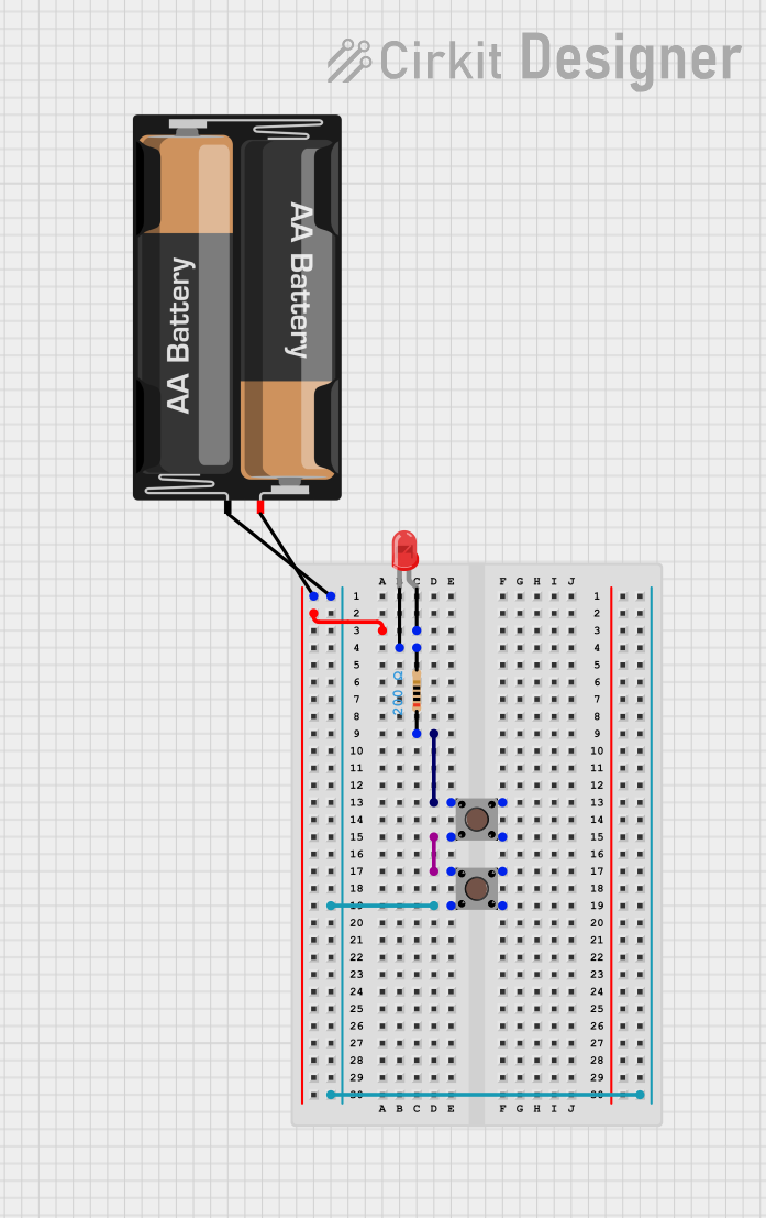
Circuit Documentation
Summary
This circuit consists of a red LED, a resistor, two pushbuttons, and a 2 x AA battery mount. The circuit is designed to control the LED using the pushbuttons. When the pushbuttons are pressed, the LED will light up, indicating the completion of the circuit.
Component List
Resistor
- Description: A resistor with a resistance of 200 Ohms.
- Pins: pin1, pin2
LED: Two Pin (red)
- Description: A red LED with two pins: anode and cathode.
- Pins: anode, cathode
Pushbutton (1)
- Description: A pushbutton with four pins.
- Pins: Pin 1 (in), Pin 2 (in), Pin 3 (out), Pin 4 (out)
Pushbutton (2)
- Description: Another pushbutton with four pins.
- Pins: Pin 1 (in), Pin 2 (in), Pin 3 (out), Pin 4 (out)
2 x AA Battery Mount
- Description: A battery mount for two AA batteries.
- Pins: +, -
Wiring Details
Resistor
- pin1 is connected to Pin 3 (out) of the first pushbutton.
- pin2 is connected to the cathode of the LED.
LED: Two Pin (red)
- anode is connected to the + pin of the battery mount.
- cathode is connected to pin2 of the resistor.
Pushbutton (1)
- Pin 1 (in) is connected to Pin 2 (in) of the second pushbutton.
- Pin 3 (out) is connected to pin1 of the resistor.
Pushbutton (2)
- Pin 1 (in) is connected to Pin 1 (in) of the first pushbutton.
- Pin 2 (in) is connected to Pin 1 (in) of the first pushbutton.
- Pin 4 (out) is connected to the - pin of the battery mount.
2 x AA Battery Mount
- + is connected to the anode of the LED.
- - is connected to Pin 4 (out) of the second pushbutton.
Code
There is no microcontroller code associated with this circuit.