
ESP32-Based Smart Weighing System with Load Sensors and HX711 Interface
View and Edit Project In Cirkit Designer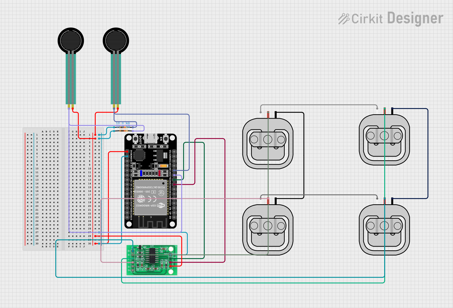
Circuit Documentation
Summary
This circuit involves an ESP32 microcontroller interfacing with multiple load sensors, force sensing resistors, and an HX711 bridge sensor interface. The ESP32 reads data from the sensors and processes it accordingly. The load sensors are connected through the HX711 interface, which amplifies the signal for the ESP32. The force sensing resistors are directly connected to the ESP32 through resistors.
Component List
ESP32 (30 pin)
- Description: A powerful microcontroller with built-in Wi-Fi and Bluetooth capabilities.
- Pins: EN, VP, VN, D34, D35, D32, D33, D25, D26, D27, D14, D12, D13, GND, Vin, D23, D22, TX0, RX0, D21, D19, D18, D5, TX2, RX2, D4, D2, D15, 3V3
Load Sensor - 50kg
- Description: A sensor used to measure weight up to 50kg.
- Pins: W, R, B
Force Sensing Resistor
- Description: A resistor whose resistance changes with applied force.
- Pins: pin 0, pin 1
HX711 - Bridge Sensor Interface
- Description: An interface for connecting bridge sensors like load cells to microcontrollers.
- Pins: E+, E-, A-, A+, B-, B+, GND - GROUND, DATA (OUT), SCK - CLOCK (IN), 3.3/3.5V Supply
Resistor (10k Ohms)
- Description: A resistor with a resistance of 10k Ohms.
- Pins: pin1, pin2
Wiring Details
ESP32 (30 pin)
- D25 is connected to SCK - CLOCK (IN) of the HX711 - Bridge Sensor Interface.
- D26 is connected to DATA (OUT) of the HX711 - Bridge Sensor Interface.
- D27 is connected to pin 0 of the Force Sensing Resistor and pin2 of the Resistor.
- D14 is connected to pin 0 of the Force Sensing Resistor and pin2 of the Resistor.
- GND is connected to GND - GROUND of the HX711 - Bridge Sensor Interface, pin1 of the Resistor, and pin1 of the Resistor.
- 3V3 is connected to pin 1 of the Force Sensing Resistor, pin 1 of the Force Sensing Resistor, and 3.3/3.5V Supply of the HX711 - Bridge Sensor Interface.
Load Sensor - 50kg
- W of one load sensor is connected to W of another load sensor.
- R of one load sensor is connected to E- of the HX711 - Bridge Sensor Interface.
- B of one load sensor is connected to B of another load sensor.
- W of another load sensor is connected to W of another load sensor.
- R of another load sensor is connected to A+ of the HX711 - Bridge Sensor Interface.
- R of another load sensor is connected to E+ of the HX711 - Bridge Sensor Interface.
- R of another load sensor is connected to A- of the HX711 - Bridge Sensor Interface.
- B of another load sensor is connected to B of another load sensor.
Force Sensing Resistor
- pin 0 of one force sensing resistor is connected to D27 of the ESP32 and pin2 of the Resistor.
- pin 0 of another force sensing resistor is connected to D14 of the ESP32 and pin2 of the Resistor.
- pin 1 of one force sensing resistor is connected to 3V3 of the ESP32.
- pin 1 of another force sensing resistor is connected to 3V3 of the ESP32.
HX711 - Bridge Sensor Interface
- SCK - CLOCK (IN) is connected to D25 of the ESP32.
- DATA (OUT) is connected to D26 of the ESP32.
- GND - GROUND is connected to GND of the ESP32, pin1 of the Resistor, and pin1 of the Resistor.
- 3.3/3.5V Supply is connected to 3V3 of the ESP32.
- E- is connected to R of one Load Sensor - 50kg.
- A+ is connected to R of another Load Sensor - 50kg.
- E+ is connected to R of another Load Sensor - 50kg.
- A- is connected to R of another Load Sensor - 50kg.
Resistor (10k Ohms)
- pin1 of one resistor is connected to GND of the ESP32 and GND - GROUND of the HX711 - Bridge Sensor Interface.
- pin2 of one resistor is connected to pin 0 of the Force Sensing Resistor and D27 of the ESP32.
- pin1 of another resistor is connected to GND of the ESP32 and GND - GROUND of the HX711 - Bridge Sensor Interface.
- pin2 of another resistor is connected to pin 0 of the Force Sensing Resistor and D14 of the ESP32.
Code
No code is provided for this circuit.