Cirkit Designer
Your all-in-one circuit design IDE
Home /
Project Documentation
Arduino Nano Controlled LED Matrix Display with Interactive Buzzer

Circuit Documentation
Summary
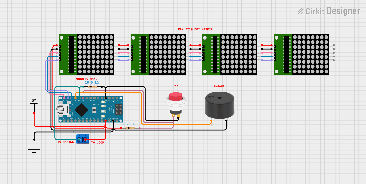
This circuit incorporates an Arduino Nano as the central microcontroller, interfaced with multiple 8x8 LED matrix modules, a buzzer, a push switch, and a couple of resistors. The Arduino Nano controls the LED matrices and the buzzer, while the push switch allows for user interaction. The resistors are used for pull-up configurations and current limiting. The circuit is powered by a 5V supply, which is distributed to the Arduino and other components.
Component List
Microcontroller
- Arduino Nano: A compact microcontroller board based on the ATmega328P, featuring digital and analog I/O pins.
LED Matrix Modules
- 8x8 LED Matrix: Four instances of an 8x8 LED matrix are used for display purposes.
Input Device
- 2Pin Push Switch: A momentary push switch used to provide input to the microcontroller.
Output Device
- Buzzer: An audible signaling device that is controlled by the Arduino Nano.
Passive Components
- Resistors: Two 10k Ohm resistors are used in the circuit for pull-up and current limiting purposes.
Power Supply Components
- Vcc: Represents the positive supply voltage (5V) in the circuit.
- GND: Represents the ground reference in the circuit.
Connectors
- Terminal PCB 2 Pin: A two-pin terminal block used for making external power connections to the circuit.
Wiring Details
Arduino Nano
- GND: Connected to the ground plane, the negative terminal of the buzzer, and one terminal of the push switch through a 10k Ohm resistor.
- D7: Connected to the other terminal of the push switch through a 10k Ohm resistor.
- D8: Connected to one terminal of the Terminal PCB 2 Pin.
- D9: Connected to the positive terminal of the buzzer.
- D10 - D12/MISO: Connected to the clk, CS, and DIN pins of the first 8x8 LED matrix, respectively.
- 5V: Connected to the Vcc terminal of the Terminal PCB 2 Pin and the vcc pin of the first 8x8 LED matrix.
8x8 LED Matrix Modules
- vcc: All matrices are connected in parallel to the 5V supply.
- DIN: The DIN pin of each matrix is connected to the DOUT pin of the previous matrix.
- clk/CLK: The clk pin of each matrix is connected to the CLK pin of the next matrix.
- CS: The CS pin of each matrix is connected to the CS pin of the next matrix.
- Gnd/gnd: All matrices are connected in parallel to the ground plane.
2Pin Push Switch
- Input +: Connected to D7 on the Arduino Nano through a 10k Ohm resistor.
- Output +: Connected to the ground plane.
Buzzer
- PIN: Connected to D9 on the Arduino Nano.
- GND: Connected to the ground plane.
Resistor (10k Ohm)
- Two resistors are used, one between the push switch and the Arduino Nano, and the other between the push switch and the ground plane.
Terminal PCB 2 Pin
- Pin A: Connected to D8 on the Arduino Nano.
- Pin B: Connected to the 5V supply.
Documented Code
Arduino Nano Code (sketch.ino)
void setup() {
  // put your setup code here, to run once:

}

void loop() {
  // put your main code here, to run repeatedly:

}
Additional Notes (documentation.txt)
No additional code documentation was provided.