
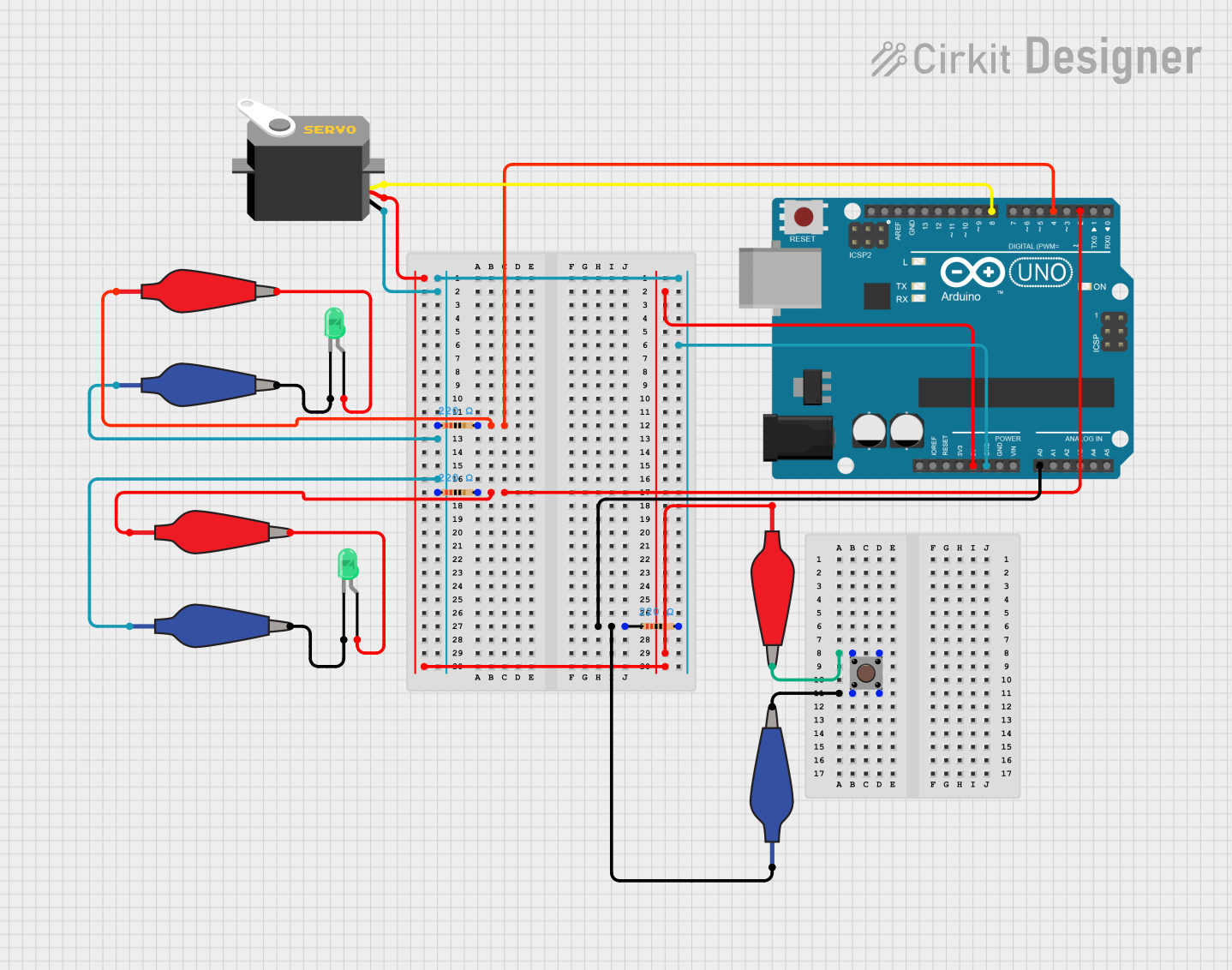
Circuit Documentation
Summary
This document provides a detailed overview of a circuit that includes an Arduino UNO microcontroller, two green LEDs, three resistors, a servo motor, a pushbutton, and several alligator clip cables for connections. The circuit is designed to interface with external components through the Arduino UNO, which is programmed to control the LEDs and the servo motor. The pushbutton is used as an input device, and the resistors are used to limit current to the LEDs.
Component List
Arduino UNO
- Microcontroller board based on the ATmega328P
- It has 14 digital input/output pins, 6 analog inputs, a 16 MHz quartz crystal, a USB connection, a power jack, an ICSP header, and a reset button.
Green LED (x2)
- Standard two-pin green light-emitting diode
- Used as an output indicator
Resistor (x3)
- 220 Ohm resistors
- Used to limit current to the LEDs
Servo Motor
- A rotary actuator or linear actuator that allows for precise control of angular or linear position, velocity, and acceleration
- It consists of a suitable motor coupled to a sensor for position feedback
Pushbutton
- A simple switch mechanism for controlling some aspect of a machine or a process
- Buttons are typically made out of hard material, usually plastic or metal
Alligator Clip Cable (x6)
- A cable with an alligator clip at one or both ends
- Used to establish temporary electrical connections
Wiring Details
Arduino UNO
- Digital Pin D4 connected to a red alligator clip cable and a 220 Ohm resistor
- Digital Pin D2 connected to a red alligator clip cable and a 220 Ohm resistor
- Analog Pin A0 connected to a blue alligator clip cable and a 220 Ohm resistor
- Digital Pin D8 connected to the pulse pin of the servo motor
- 5V Pin connected to the VCC pin of the servo motor and a red alligator clip cable
- GND Pin connected to the GND pin of the servo motor, three 220 Ohm resistors, and two blue alligator clip cables
Green LED (x2)
- Anode connected to a red alligator clip cable
- Cathode connected to a blue alligator clip cable
Resistor (x3)
- One side connected to an Arduino UNO pin (D4, D2, or A0) or the GND pin
- The other side connected to an alligator clip cable (red or blue)
Servo Motor
- VCC connected to the 5V pin of the Arduino UNO
- GND connected to the GND pin of the Arduino UNO
- Pulse connected to Digital Pin D8 of the Arduino UNO
Pushbutton
- Pin 1 (in) connected to a red alligator clip cable
- Pin 2 (in) connected to a blue alligator clip cable
- Pin 3 (out) connected to a red alligator clip cable
- Pin 4 (out) connected to a blue alligator clip cable
Alligator Clip Cable (x6)
- Used to connect various components to the Arduino UNO and to each other
Documented Code
Arduino UNO Code (sketch.ino)
void setup() {
  // put your setup code here, to run once:

}

void loop() {
  // put your main code here, to run repeatedly:

}
Note: The provided code is a template and does not contain any functional code to control the circuit components. It needs to be populated with the appropriate setup and loop code to interact with the connected devices.