
Arduino UNO Controlled Stepper Motor with Pushbutton Interface
View and Edit Project In Cirkit Designer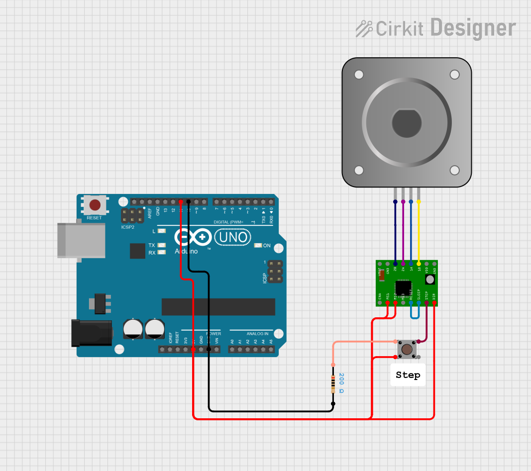
Circuit Documentation
Summary
This circuit involves an Arduino UNO microcontroller, a pushbutton, an A4988 stepper motor driver, a bipolar stepper motor (NEMA 17), and a resistor. The Arduino UNO controls the stepper motor driver, which in turn drives the stepper motor. The pushbutton is used to provide input to the Arduino, and the resistor is used for current limiting.
Component List
Arduino UNO
- Description: A microcontroller board based on the ATmega328P.
- Pins: UNUSED, IOREF, Reset, 3.3V, 5V, GND, Vin, A0, A1, A2, A3, A4, A5, SCL, SDA, AREF, D13, D12, D11, D10, D9, D8, D7, D6, D5, D4, D3, D2, D1, D0
Pushbutton
- Description: A simple pushbutton switch.
- Pins: Pin 3 (out), Pin 4 (out), Pin 1 (in), Pin 2 (in)
A4988 Stepper Motor Driver Carrier
- Description: A carrier board for the A4988 stepper motor driver.
- Pins: ENABLE, MS1, MS2, MS3, RESET, SLEEP, STEP, DIR, GND, VCC, 1B, 1A, 2A, 2B, VMOT
Bipolar Stepper Motor (NEMA 17)
- Description: A bipolar stepper motor.
- Pins: A-, A+, B+, B-
Resistor
- Description: A resistor with a resistance of 200 Ohms.
- Pins: pin1, pin2
- Properties:
- Resistance: 200 Ohms
Wiring Details
Arduino UNO
- D11: Connected to Pushbutton Pin 4 (out)
- 5V: Connected to Pushbutton Pin 4 (out)
- D10: Connected to Resistor pin2
- GND: Connected to Resistor pin2
Pushbutton
- Pin 4 (out): Connected to Arduino UNO D11 and 5V
- Pin 1 (in): Connected to A4988 Stepper Motor Driver Carrier STEP
- Pin 2 (in): Connected to Resistor pin1
A4988 Stepper Motor Driver Carrier
- MS1: Connected to MS2 and DIR
- MS2: Connected to MS1 and DIR
- DIR: Connected to MS1 and MS2
- STEP: Connected to Pushbutton Pin 1 (in)
- RESET: Connected to SLEEP
- SLEEP: Connected to RESET
- 1B: Connected to Bipolar Stepper Motor (NEMA 17) B-
- 1A: Connected to Bipolar Stepper Motor (NEMA 17) B+
- 2A: Connected to Bipolar Stepper Motor (NEMA 17) A+
- 2B: Connected to Bipolar Stepper Motor (NEMA 17) A-
Bipolar Stepper Motor (NEMA 17)
- B-: Connected to A4988 Stepper Motor Driver Carrier 1B
- B+: Connected to A4988 Stepper Motor Driver Carrier 1A
- A+: Connected to A4988 Stepper Motor Driver Carrier 2A
- A-: Connected to A4988 Stepper Motor Driver Carrier 2B
Resistor
- pin1: Connected to Pushbutton Pin 2 (in)
- pin2: Connected to Arduino UNO D10 and GND
Code Documentation
Arduino UNO Code
void setup() {
  // put your setup code here, to run once:
  pinMode(10, OUTPUT);
  pinMode(11, OUTPUT);

  digitalWrite(10, LOW);
  digitalWrite(11, HIGH);
}

void loop() {
  // put your main code here, to run repeatedly:

}
This code sets up the Arduino UNO by configuring pins 10 and 11 as outputs. In the setup function, pin 10 is set to LOW and pin 11 is set to HIGH. The loop function is currently empty and can be used to add additional functionality as needed.