Cirkit Designer
Your all-in-one circuit design IDE
Home /
Project Documentation
ESP32-CAM and Arduino Nano Controlled CNC Machine with Wi-Fi and Stepper Motors
Circuit Documentation
Summary
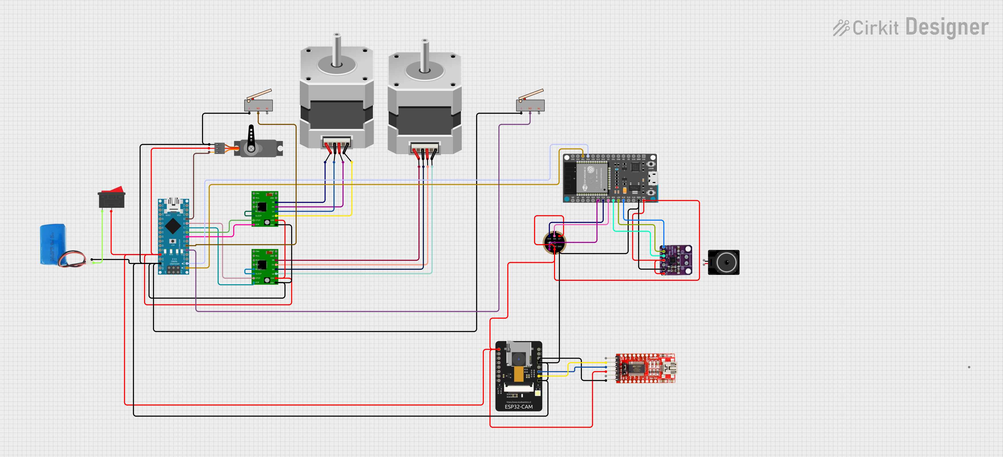
The circuit in question appears to be a complex system involving motor control, audio processing, and wireless communication capabilities. It includes stepper motors controlled by A4988 stepper motor driver carriers, an ESP32-CAM module for wireless camera functionality, an INMP441 microphone for audio input, a MAX98375 audio amplifier for driving a loudspeaker, and an Arduino Nano for general-purpose I/O and interfacing. The system is powered by a 5V battery and includes limit switches for position sensing and a servo motor for additional movement control.
Component List
A4988 Stepper Motor Driver Carrier
- Description: A module for driving bipolar stepper motors.
- Pins: ENABLE, MS1, MS2, MS3, RESET, SLEEP, STEP, DIR, GND, VCC, 1B, 1A, 2A, 2B, VMOT
Stepper Motor (Bipolar)
- Description: A bipolar stepper motor for precision movement.
- Pins: D, B, C, A
ESP32 - CAM
- Description: An ESP32-based module with camera functionality.
- Pins: 5V, GND, IO12, IO13, IO15, IO14, IO2, IO4, VOT, VOR, VCC, IO0, IO16, 3V3
INMP441 FRONT MIC
- Description: A digital I2S output microphone.
- Pins: L/R, WS, SCK, SD, VDD, GND
Loudspeaker
- Description: An audio output device.
- Pins: pin1, pin2
5v Battery
- Description: A power source for the circuit.
- Pins: positive, negative
Rocker Switch
- Description: A switch to control power flow.
- Pins: 1, 2
MAX98375
- Description: An audio amplifier for driving speakers.
- Pins: LRC, BLCK, DIN, GAIN, SD, GND, VIN
FTDI Programmer
- Description: A USB to serial converter for programming.
- Pins: DTR, RX, TX, VCC, CTS, GND
Limit Switch
- Description: A switch that is actuated by the motion of a machine part or presence of an object.
- Pins: C, NO, NC
Arduino Nano
- Description: A small, complete, and breadboard-friendly board based on the ATmega328.
- Pins: D1/TX, D0/RX, RESET, GND, D2, D3, D4, D5, D6, D7, D8, D9, D10, D11/MOSI, D12/MISO, VIN, 5V, A7, A6, A5, A4, A3, A2, A1, A0, AREF, 3V3, D13/SCK
ESP32 Devkit V1
- Description: An ESP32-based development board.
- Pins: 3V3, GND, D15, D2, D4, RX2, TX2, D5, D18, D19, D21, RX0, TX0, D22, D23, EN, VP, VN, D34, D35, D32, D33, D25, D26, D27, D14, D12, D13, VIN
Servo
- Description: A rotary actuator or linear actuator that allows for precise control of angular or linear position.
- Pins: GND, VCC, PWM
Wiring Details
A4988 Stepper Motor Driver Carrier
- ENABLE: Not connected
- MS1, MS2, MS3: Not connected (microstepping configuration pins)
- RESET: Connected to SLEEP
- SLEEP: Connected to RESET
- STEP: Connected to Arduino Nano D6 or D8 (depending on the instance)
- DIR: Connected to Arduino Nano D5 or D7 (depending on the instance)
- GND: Connected to system ground
- VCC: Connected to 5V through Rocker Switch
- 1B, 1A, 2A, 2B: Connected to corresponding pins on Stepper Motor (Bipolar)
- VMOT: Not connected (motor power supply)
Stepper Motor (Bipolar)
- D, B, C, A: Connected to corresponding pins on A4988 Stepper Motor Driver Carrier
ESP32 - CAM
- 5V: Connected to 5V power supply
- GND: Connected to system ground
- IO12, IO13, IO15, IO14, IO2, IO4: Not connected (general purpose I/O)
- VOT: Connected to FTDI Programmer RX
- VOR: Connected to FTDI Programmer TX
- VCC: Not connected (3.3V power supply)
- IO0, IO16: Not connected (general purpose I/O)
- 3V3: Not connected (3.3V power output)
INMP441 FRONT MIC
- L/R: Connected to 5V power supply
- WS: Connected to ESP32 Devkit V1 D25
- SCK: Connected to ESP32 Devkit V1 D33
- SD: Connected to ESP32 Devkit V1 D32
- VDD: Connected to 5V power supply
- GND: Connected to system ground
Loudspeaker
- pin1, pin2: Connected to MAX98375 audio amplifier output
5v Battery
- positive: Connected to Rocker Switch pin 1
- negative: Connected to system ground
Rocker Switch
- 1: Connected to 5V battery positive
- 2: Connected to system 5V power rail
MAX98375
- LRC: Connected to ESP32 Devkit V1 D14
- BLCK: Connected to ESP32 Devkit V1 D27
- DIN: Connected to ESP32 Devkit V1 D26
- GAIN: Connected to 5V power supply
- SD: Not connected (shutdown control)
- GND: Connected to system ground
- VIN: Connected to 5V power supply
FTDI Programmer
- DTR: Not connected
- RX: Connected to ESP32 - CAM VOT
- TX: Connected to ESP32 - CAM VOR
- VCC: Connected to 5V power supply
- CTS: Not connected
- GND: Connected to system ground
Limit Switch
- C: Connected to system ground
- NO: Connected to Arduino Nano D2 or D3 (depending on the instance)
- NC: Not connected
Arduino Nano
- D1/TX: Connected to ESP32 Devkit V1 TX0
- D0/RX: Connected to ESP32 Devkit V1 RX0
- RESET, AREF, 3V3: Not connected
- GND: Connected to system ground
- D2, D3: Connected to Limit Switch NO (depending on the instance)
- D5, D6, D7, D8: Connected to A4988 Stepper Motor Driver Carrier DIR and STEP (depending on the instance)
- D9: Connected to Servo PWM
- D10, D11/MOSI, D12/MISO, D13/SCK: Not connected (SPI interface)
- VIN: Connected to 5V power supply
- 5V: Connected to system 5V power rail
- A7, A6, A5, A4, A3, A2, A1, A0: Not connected (analog inputs)
ESP32 Devkit V1
- 3V3, VP, VN, EN, D34, D35, D15, D2, D4, RX2, TX2, D5, D18, D19, D21, D22, D23, D12, D13: Not connected
- GND: Connected to system ground
- RX0: Connected to Arduino Nano D0/RX
- TX0: Connected to Arduino Nano D1/TX
- D25: Connected to INMP441 FRONT MIC WS
- D33: Connected to INMP441 FRONT MIC SCK
- D32: Connected to INMP441 FRONT MIC SD
- D26: Connected to MAX98375 DIN
- D27: Connected to MAX98375 BLCK
- D14: Connected to MAX98375 LRC
- VIN: Connected to 5V power supply
Servo
- GND: Connected to system ground
- VCC: Connected to 5V power supply
- PWM: Connected to Arduino Nano D9
Documented Code
ESP32 - CAM Code (Instance ID: b48c5a91-c825-4549-af62-cc3ca2f782df)
#include <WebServer.h>
#include <WiFi.h>
#include <esp32cam.h>

const char* WIFI_SSID = "Your SSID";
const char* WIFI_PASS = "Your Password";

WebServer server(80);

static auto loRes = esp32cam::Resolution::find(320, 240);
static auto midRes =