Cirkit Designer
Your all-in-one circuit design IDE
Home /
Project Documentation
ESP32-Based Smart Weather Station with DHT11 Sensor and I2C LCD Display
Circuit Documentation
Summary
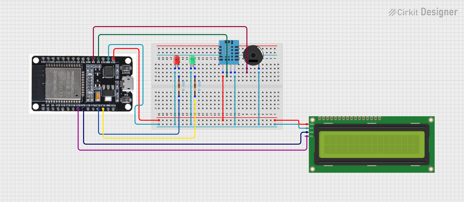
This document provides a detailed overview of a circuit that includes a DHT11 Humidity and Temperature Sensor, a 16x2 I2C LCD, a Piezo Buzzer, two LEDs (red and green), two Resistors, and an ESP32 microcontroller. The circuit is designed to read environmental data, display it on an LCD, and provide visual and auditory feedback using LEDs and a buzzer.
Component List
DHT11 Humidity and Temperature Sensor
- Description: Measures humidity and temperature.
- Pins: VDD, DATA, NULL, GND
16x2 I2C LCD
- Description: Displays data in a 16x2 character format using I2C communication.
- Pins: GND, VCC, SDA, SCL
Piezo Buzzer
- Description: Emits sound when activated.
- Pins: pin 1, pin 2
LED: Two Pin (red)
- Description: Emits red light when powered.
- Pins: cathode, anode
LED: Two Pin (green)
- Description: Emits green light when powered.
- Pins: cathode, anode
Resistor (200 Ohms)
- Description: Limits current flow.
- Pins: pin1, pin2
- Properties: Resistance: 200 Ohms
ESP32
- Description: Microcontroller with Wi-Fi and Bluetooth capabilities.
- Pins: EN, VP, VN, D34, D35, D32, D33, D25, D26, D27, D14, D12, D13, GND, VIN, 3V3, D15, D2, D4, RX2, TX2, D5, D18, D19, D21, RX0, TX0, D22, D23, BOOT
Wiring Details
DHT11 Humidity and Temperature Sensor
- VDD connected to ESP32 3V3
- DATA connected to ESP32 D2
- GND connected to common ground
16x2 I2C LCD
- GND connected to ESP32 3V3
- VCC connected to common ground
- SDA connected to ESP32 D26
- SCL connected to ESP32 D25
Piezo Buzzer
- pin 1 connected to ESP32 D4
- pin 2 connected to common ground
LED: Two Pin (red)
- anode connected to Resistor pin1
- cathode connected to common ground
LED: Two Pin (green)
- anode connected to Resistor pin1
- cathode connected to common ground
Resistor (200 Ohms)
- Resistor 1:
- pin1 connected to LED (red) anode
- pin2 connected to ESP32 D12
- Resistor 2:
- pin1 connected to LED (green) anode
- pin2 connected to ESP32 D13
ESP32
- GND connected to common ground
- 3V3 connected to DHT11 VDD and 16x2 I2C LCD GND
- D2 connected to DHT11 DATA
- D4 connected to Piezo Buzzer pin 1
- D12 connected to Resistor 1 pin2
- D13 connected to Resistor 2 pin2
- D25 connected to 16x2 I2C LCD SCL
- D26 connected to 16x2 I2C LCD SDA
Code
No code provided for this circuit.