
Circuit Documentation
Summary
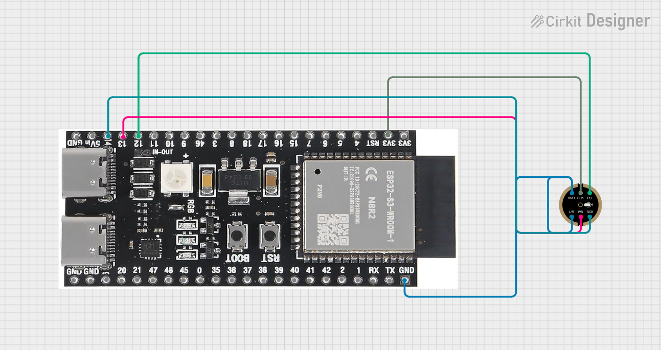
This document provides a detailed overview of a circuit that includes an ESP32-S3-DevKitC-1-N8R2 microcontroller and an INMP441 microphone. The ESP32 reads audio data from the INMP441 microphone using the I2S protocol and prints the audio data to the serial monitor.
Component List
ESP32-S3-DevKitC-1-N8R2
- Description: A development board featuring the ESP32-S3 microcontroller.
- Pins: GND, 5Vin, 14, 13, 12, 11, 10, 9, 46, 3, 8, 18, 17, 16, 15, 7, 6, 5, 4, 3v3, TX, RX, 1, 2, 42, 41, 40, 39, 38, 37, 36, 35, 0, 45, 48, 47, 21, 20, 19
- Purpose in Circuit: Microcontroller to read audio data from the microphone and print it to the serial monitor.
INMP441 FRONT MIC
- Description: A high-performance, low-power, digital-output, omnidirectional MEMS microphone.
- Pins: L/R, WS, SCK, SD, VDD, GND
- Purpose in Circuit: To capture audio data and send it to the ESP32 microcontroller via the I2S protocol.
Wiring Details
ESP32-S3-DevKitC-1-N8R2
- Pin 14 is connected to INMP441 SCK.
- Pin 13 is connected to INMP441 WS.
- Pin 12 is connected to INMP441 SD.
- Pin 3v3 is connected to INMP441 VDD.
- Pin GND is connected to INMP441 L/R and INMP441 GND.
INMP441 FRONT MIC
- Pin SCK is connected to ESP32-S3-DevKitC-1-N8R2 Pin 14.
- Pin WS is connected to ESP32-S3-DevKitC-1-N8R2 Pin 13.
- Pin SD is connected to ESP32-S3-DevKitC-1-N8R2 Pin 12.
- Pin VDD is connected to ESP32-S3-DevKitC-1-N8R2 Pin 3v3.
- Pin L/R and Pin GND are connected to ESP32-S3-DevKitC-1-N8R2 Pin GND.
Code Documentation
/*
 * This Arduino Sketch is for an ESP32-S3-DevKitC-1-N8R2 connected to an INMP441
 * microphone. The ESP32 reads audio data from the INMP441 microphone using I2S
 * protocol and prints the audio data to the serial monitor.
 */

#include <Wire.h>
#include <I2S.h>

// I2S pins
#define I2S_WS 13
#define I2S_SCK 14
#define I2S_SD 12

void setup() {
  // Initialize serial communication
  Serial.begin(115200);
  while (!Serial);
  Serial.println("I2S Microphone Test");

  // Initialize I2S
  if (!I2S.begin(I2S_PHILIPS_MODE, 16000, 32)) {
    Serial.println("Failed to initialize I2S!");
    while (1);
  }

  // Configure I2S pins
  I2S.setPins(I2S_SCK, I2S_WS, I2S_SD);
}

void loop() {
  int32_t sample = 0;
  size_t bytesRead = I2S.read((uint8_t *)&sample, sizeof(sample));

  if (bytesRead > 0) {
    Serial.println(sample);
  }
}
Code Explanation
- Libraries Included:
Wire.h: For I2C communication (not used in this sketch but included for completeness).I2S.h: For I2S communication.
- Pin Definitions:
I2S_WSis defined as pin 13.I2S_SCKis defined as pin 14.I2S_SDis defined as pin 12.
- Setup Function:
- Initializes serial communication at a baud rate of 115200.
- Waits for the serial port to be available.
- Prints "I2S Microphone Test" to the serial monitor.
- Initializes the I2S interface in Philips mode with a sample rate of 16000 Hz and a bit depth of 32 bits.
- Configures the I2S pins.
- Loop Function:
- Reads a 32-bit audio sample from the I2S interface.
- If a sample is successfully read, it prints the sample to the serial monitor.