Arduino Mega 2560 Automated Plant Watering System with Environmental Monitoring
Circuit Documentation
Summary
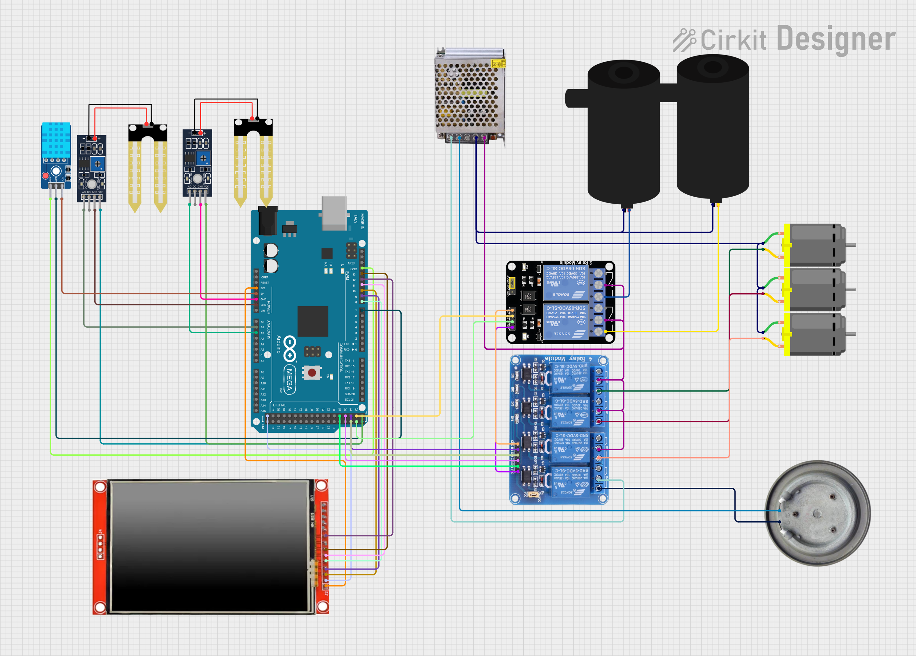
This circuit is designed to interface various components with an Arduino Mega 2560 microcontroller. The components include a humidity sensor (YL-69), a water pump, a 4-channel relay module, DC motors, a DHT11 temperature and humidity sensor, an LCD TFT screen (ILI9488 HD), a heater element, and a 12V 5A power supply. The circuit is likely intended for an automated environmental control system, possibly for applications like a greenhouse where monitoring and adjusting temperature, humidity, and watering are crucial.
Component List
Microcontroller
- Arduino Mega 2560: A microcontroller board based on the ATmega2560 with a wide range of input/output options.
Sensors
- Humidity YL-69: A soil moisture sensor that can provide digital or analog signals indicating soil moisture levels.
- DHT11 Sensor V2: A digital temperature and humidity sensor with a calibrated digital signal output.
Actuators
- Water Pump: An electric pump for moving water.
- DC Motor: A simple electric motor that runs on direct current.
- Heater Element: An electrical heating element that converts electrical energy into heat.
Display
- LCD TFT screen ILI9488 HD: A color graphic LCD screen with a touch panel interface for display and user input.
Power Supply
- POWER SUPPLY 12V 5AMP: A power supply unit that provides 12V DC output with a maximum current of 5A.
Relays
- Relay 4 Channel 5v: A 4-channel relay module for controlling high power or high voltage devices.
- Relay Module 2 Channel: A 2-channel relay module for controlling devices that require isolation from the microcontroller.
Wiring Details
Arduino Mega 2560
- 3V3: Connected to the LCD TFT screen ILI9488 HD VCC.
- 5V: Connected to the DHT11 Sensor V2 VCC, Humidity YL-69 VCC, Relay Module 2 Channel VCC, and Relay 4 Channel 5v VCC.
- GND: Common ground shared with all components.
- A1: Connected to Humidity YL-69 A0 (analog output).
- A2: Connected to another Humidity YL-69 A0 (analog output).
- D7 PWM: Connected to DHT11 Sensor V2 DAT (data pin).
- D8 PWM: Connected to LCD TFT screen ILI9488 HD D/C (data/command control pin).
- D9 PWM: Connected to LCD TFT screen ILI9488 HD RST (reset pin).
- D10 PWM: Connected to LCD TFT screen ILI9488 HD CS (chip select pin).
- D11 PWM: Connected to LCD TFT screen ILI9488 HD SDI(MOSI) (master out, slave in pin).
- D12 PWM: Connected to LCD TFT screen ILI9488 HD SDO(MISO) (master in, slave out pin).
- D13 PWM: Connected to LCD TFT screen ILI9488 HD SCK (serial clock pin).
- D22: Connected to Relay Module 2 Channel IN1.
- D23: Connected to Relay Module 2 Channel IN2.
- D24: Connected to Relay 4 Channel 5v IN1.
- D25: Connected to Relay 4 Channel 5v IN2.
- D26: Connected to Relay 4 Channel 5v IN3.
- D28: Connected to Relay 4 Channel 5v IN4.
Humidity YL-69
- A0: Analog output connected to Arduino Mega 2560 A1 or A2.
- D0: Not connected in this configuration.
- GND: Connected to Arduino Mega 2560 GND.
- VCC: Connected to Arduino Mega 2560 5V.
Water Pump
- Positive: Connected to Relay Module 2 Channel NO1 or NO2.
- Negative: Common ground shared with DC Motors and POWER SUPPLY 12V 5AMP GND (DC).
DC Motor
- Pin 1: Common ground shared with Water Pump Negative and POWER SUPPLY 12V 5AMP GND (DC).
- Pin 2: Connected to Relay 4 Channel 5v NO1, NO2, or NO3.
DHT11 Sensor V2
- GND: Connected to Arduino Mega 2560 GND.
- DAT: Connected to Arduino Mega 2560 D7 PWM.
- VCC: Connected to Arduino Mega 2560 5V.
LCD TFT screen ILI9488 HD
- VCC (3.3~5V): Connected to Arduino Mega 2560 3V3.
- GND: Connected to Arduino Mega 2560 GND.
- CS: Connected to Arduino Mega 2560 D10 PWM.
- RST: Connected to Arduino Mega 2560 D9 PWM.
- D/C: Connected to Arduino Mega 2560 D8 PWM.
- SDI(MOSI): Connected to Arduino Mega 2560 D11 PWM.
- SCK: Connected to Arduino Mega 2560 D13 PWM.
- SDO(MISO): Connected to Arduino Mega 2560 D12 PWM.
- PEN, TDO, TDI, BL, TCS, TCK: Not connected in this configuration.
Heater Element
- VCC: Connected to Relay 4 Channel 5v NO4.
- GND: Connected to POWER SUPPLY 12V 5AMP 220V Negative Pole (AC).
Relay 4 Channel 5v & Relay Module 2 Channel
- GND: Common ground shared with Arduino Mega 2560 GND.
- VCC: Connected to Arduino Mega 2560 5V.
- IN1, IN2, IN3, IN4: Controlled by Arduino Mega 2560 digital pins D24, D25, D26, and D28 respectively.
- COM1, COM2, COM3, COM4: Connected to POWER SUPPLY 12V 5AMP 12V-24V Output (DC).
- NO1, NO2, NO3, NO4: Connected to DC Motors pin 2 and Heater Element VCC.
POWER SUPPLY 12V 5AMP
- 220V Positive Pole (AC): Connected to Relay 4 Channel 5v COM4.
- 220V Negative Pole (AC): Connected to Heater Element GND.
- GND (DC): Common ground shared with Water Pump Negative and DC Motors pin 1.
- 12V-24V Output (DC): Connected to Relay 4 Channel 5v COM1, COM2, COM3, and Relay Module 2 Channel COM.
Documented Code
void setup() {
  // put your setup code here, to run once:

}

void loop() {
  // put your main code here, to run repeatedly:

}
The provided code is a template with empty setup() and loop() functions, which are the standard structure for Arduino sketches. The setup() function is intended to contain initialization code that runs once when the microcontroller is powered on or reset. The loop() function is for code that runs continuously as long as the microcontroller is powered. Additional code would be required to control the components as per the wiring details and to implement the desired functionality of the circuit.