
Arduino and ESP8266-Based Multi-Thermocouple Temperature Monitoring System with Wi-Fi Connectivity
View and Edit Project In Cirkit Designer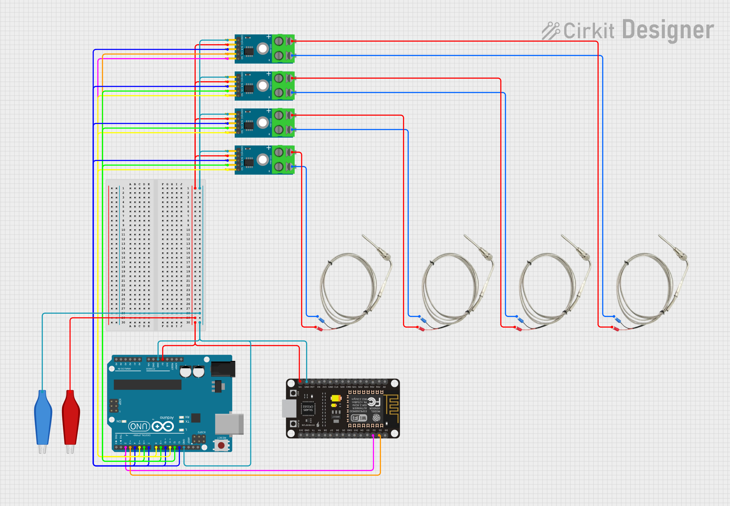
Circuit Documentation
Summary
This circuit involves an Arduino UNO microcontroller interfacing with multiple MAX6675 thermocouple modules and an ESP8266 NodeMCU. The purpose of the circuit is to read temperature data from thermocouples and potentially transmit this data wirelessly using the ESP8266. The Arduino UNO is the central controller, managing the communication with the MAX6675 modules and reading temperature data.
Component List
Arduino UNO
- Description: A microcontroller board based on the ATmega328P.
- Pins: UNUSED, IOREF, Reset, 3.3V, 5V, GND, Vin, A0, A1, A2, A3, A4, A5, SCL, SDA, AREF, D13, D12, D11, D10, D9, D8, D7, D6, D5, D4, D3, D2, D1, D0
MAX6675 Module
- Description: A digital thermocouple temperature sensor module.
- Pins: GND, VCC, SCK, CS, SO, -, +
Thermocouple
- Description: A sensor used to measure temperature.
- Pins: VCC, GND
ESP8266 NodeMCU
- Description: A low-cost Wi-Fi microchip with full TCP/IP stack and microcontroller capability.
- Pins: D0, D1, D2, D3, D4, 3V3, GND, D5, D6, D7, D8, RX, TX, A0, RSV, SD3, SD2, SD1, CMD, SD0, CLK, EN, RST, VIN
AdaGator Side Red
- Description: A wire used for connections.
- Pins: wire
AdaGator Side Blue
- Description: A wire used for connections.
- Pins: wire
Wiring Details
Arduino UNO
- 5V: Connected to VCC of all MAX6675 Modules and AdaGator Side Red.
- GND: Connected to GND of all MAX6675 Modules, AdaGator Side Blue, and ESP8266 NodeMCU.
- D13: Connected to SCK of MAX6675 Module.
- D12: Connected to CS of MAX6675 Module.
- D11: Connected to SO of MAX6675 Module.
- D10: Connected to SCK of another MAX6675 Module.
- D9: Connected to CS of another MAX6675 Module.
- D8: Connected to SO of another MAX6675 Module.
- D7: Connected to SCK of another MAX6675 Module.
- D6: Connected to CS of another MAX6675 Module.
- D5: Connected to SO of another MAX6675 Module.
- D4: Connected to SCK of another MAX6675 Module.
- D3: Connected to CS of another MAX6675 Module and D1 of ESP8266 NodeMCU.
- D2: Connected to SO of another MAX6675 Module and D2 of ESP8266 NodeMCU.
MAX6675 Module
- VCC: Connected to 5V of Arduino UNO and AdaGator Side Red.
- GND: Connected to GND of Arduino UNO and AdaGator Side Blue.
- SCK: Connected to D13, D10, D7, and D4 of Arduino UNO.
- CS: Connected to D12, D9, D6, and D3 of Arduino UNO.
- SO: Connected to D11, D8, D5, and D2 of Arduino UNO.
- -: Connected to GND of Thermocouples.
- +: Connected to VCC of Thermocouples.
Thermocouple
- GND: Connected to - of MAX6675 Modules.
- VCC: Connected to + of MAX6675 Modules.
ESP8266 NodeMCU
- VIN: Connected to 5V of Arduino UNO.
- GND: Connected to GND of Arduino UNO.
- D1: Connected to D3 of Arduino UNO.
- D2: Connected to D2 of Arduino UNO.
AdaGator Side Red
- wire: Connected to 5V of Arduino UNO and VCC of all MAX6675 Modules.
AdaGator Side Blue
- wire: Connected to GND of Arduino UNO and GND of all MAX6675 Modules.
Documented Code
Arduino UNO Code
#include "max6675.h"

int thermoDO = 12;
int thermoCS = 10;
int thermoCLK = 13;

MAX6675 thermocouple(thermoCLK, thermoCS, thermoDO); // initializing communication between Arduino and MAX6675 module

void setup() {
  Serial.begin(9600);
  delay(500); // wait for the sensor to stabilize
  Serial.println("MAX6675 Thermocouple Test");
}

void loop() {
  // Read temperature in Celsius
  Serial.print("Suhu: ");
  Serial.print(thermocouple.readCelsius()); // read the temperature in Celsius
  Serial.println(" °C");
  delay(1000); // wait 1 second for the next reading
}
This code initializes the MAX6675 thermocouple module and reads the temperature in Celsius, printing it to the serial monitor every second.