
Arduino and ESP-8266 Based Flame Detection and Climate Monitoring System
View and Edit Project In Cirkit Designer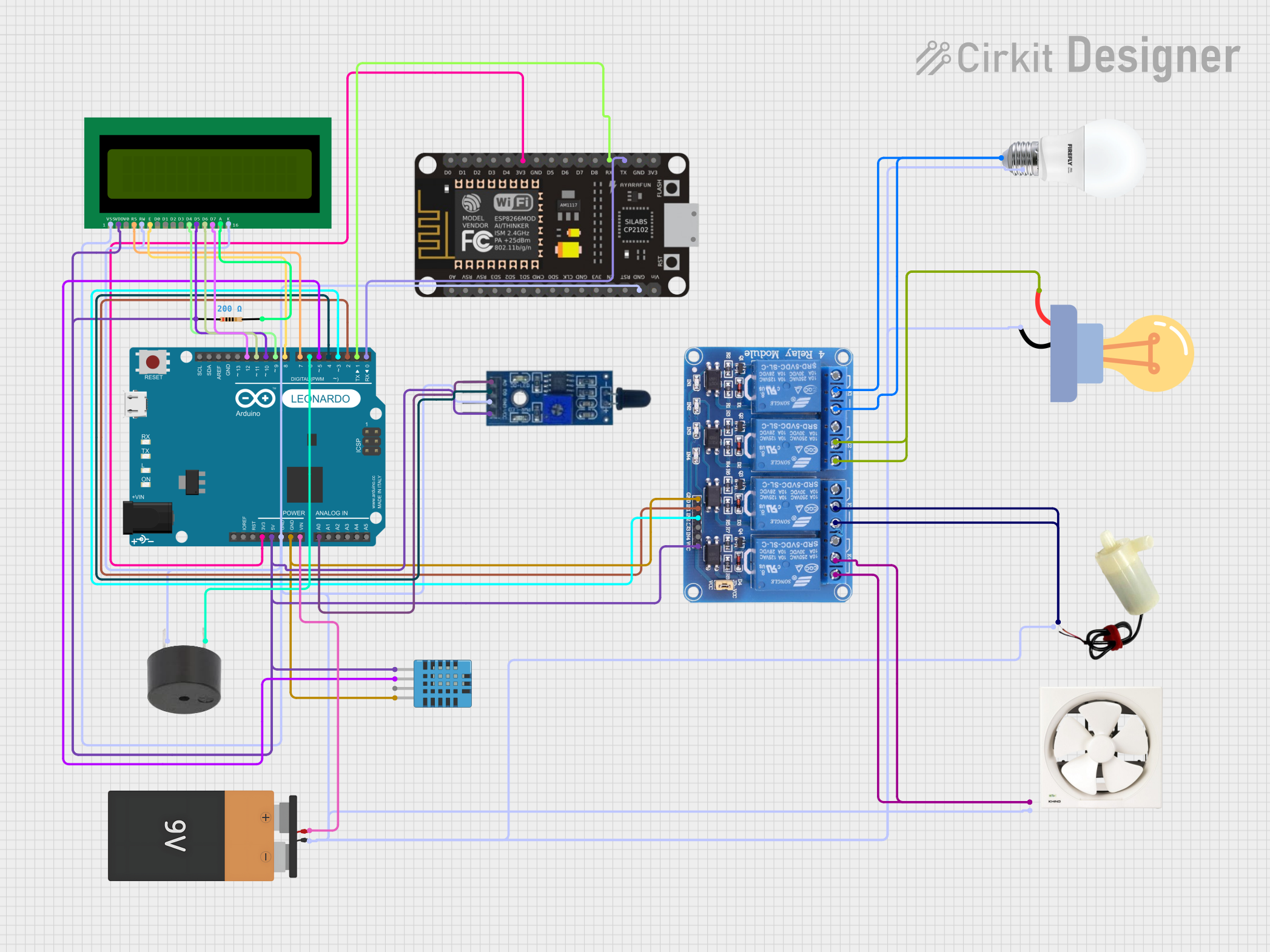
Circuit Documentation
Summary
This circuit integrates various components controlled by an Arduino Leonardo (Rev3b) microcontroller. The system includes communication with an ESP-8266 Controller, a 4-channel relay module to control power to devices such as a bulb, an LED bulb, a water pump, and an exhaust fan. It also features a 16X2 LCD for display, a flame sensor for fire detection, a DHT11 sensor for temperature and humidity readings, a buzzer for audible alerts, and a 9V battery as the power source. The circuit is designed to monitor environmental conditions and control connected devices accordingly.
Component List
- Arduino Leonardo (Rev3b): A microcontroller board based on the ATmega32u4, with various digital and analog I/O pins.
- ESP-8266 Controller: A Wi-Fi microcontroller module used for wireless communication.
- Relay 4 Channel 5v: A module with 4 relays to control high power devices.
- 16X2 LCD: A liquid crystal display for showing information.
- Flame Sensor: A sensor to detect fire or flame presence.
- DHT11 Humidity and Temperature Sensor: A sensor for measuring ambient temperature and humidity.
- Resistor (200 Ohms): A component used to limit current or divide voltages.
- BULB: A generic light bulb.
- LED bulb AC / Bombillo AC: An LED bulb designed for AC power.
- Buzzer: An audio signaling device.
- Battery 9V: A power source for the circuit.
- 5v mini water pump: A pump for moving water, powered by 5V.
- Exhaust Fan 12": A fan used to ventilate air.
Wiring Details
Arduino Leonardo (Rev3b)
- D0/RX connected to ESP-8266 Controller TX
- D1/TX connected to ESP-8266 Controller RX
- D2/SDA connected to Relay 4 Channel 5v IN1
- D3 PWM/SCL connected to Relay 4 Channel 5v IN2
- D4/A6 connected to Flame Sensor D0
- D5 PWM connected to DHT11 Humidity and Temperature Sensor DATA
- D6 PWM/A7 connected to Buzzer PIN
- D7 connected to 16X2 LCD RS
- 3V3 connected to ESP-8266 Controller 3V3
- 5V connected to DHT11 Sensor VDD, Relay 4 Channel 5v VCC, 16X2 LCD VDD, Resistor pin1, Flame Sensor VCC
- GND connected to various GND pins on other components
- VIN connected to Battery 9V VCC
- A0 connected to Flame Sensor A0
- D8/A8 connected to 16X2 LCD E
- D9 PWM/A9 connected to 16X2 LCD D4
- D10 PWM/A10 connected to 16X2 LCD D5
- D11 PWM connected to 16X2 LCD D6
- D12/A11 connected to 16X2 LCD D7
ESP-8266 Controller
- 3V3 connected to Arduino Leonardo 3V3
- GND connected to common GND
- RX connected to Arduino Leonardo D1/TX
- TX connected to Arduino Leonardo D0/RX
Relay 4 Channel 5v
- IN1 connected to Arduino Leonardo D2/SDA
- IN2 connected to Arduino Leonardo D3 PWM/SCL
- VCC connected to Arduino Leonardo 5V
- GND connected to common GND
- NO1, COM1 connected to BULB +
- NO2, COM2 connected to LED bulb AC / Bombillo AC +
- NO3, COM3 connected to 5v mini water pump positive pin
- NO4, COM4 connected to Exhaust Fan 12" Live
16X2 LCD
- VSS, K, RW connected to common GND
- VDD connected to Arduino Leonardo 5V
- RS connected to Arduino Leonardo D7
- E connected to Arduino Leonardo D8/A8
- D4 connected to Arduino Leonardo D9 PWM/A9
- D5 connected to Arduino Leonardo D10 PWM/A10
- D6 connected to Arduino Leonardo D11 PWM
- D7 connected to Arduino Leonardo D12/A11
- A connected to Resistor pin2
Flame Sensor
- VCC connected to Arduino Leonardo 5V
- GND connected to common GND
- D0 connected to Arduino Leonardo D4/A6
- A0 connected to Arduino Leonardo A0
DHT11 Humidity and Temperature Sensor
- VDD connected to Arduino Leonardo 5V
- DATA connected to Arduino Leonardo D5 PWM
- GND connected to common GND
Resistor (200 Ohms)
- pin1 connected to Arduino Leonardo 5V
- pin2 connected to 16X2 LCD A
Buzzer
- PIN connected to Arduino Leonardo D6 PWM/A7
- GND connected to common GND
Battery 9V
- VCC connected to Arduino Leonardo VIN
- GND connected to common GND
5v mini water pump
- positive pin connected to Relay 4 Channel 5v NO3, COM3
- negative pin connected to common GND
Exhaust Fan 12"
- Live connected to Relay 4 Channel 5v NO4, COM4
- Neutral connected to common GND
Documented Code
// Pin definitions
const int relay1Pin = 2; // Relay IN1
const int relay2Pin = 3; // Relay IN2
const int flameSensorAnalogPin = A0; // Flame Sensor A0
const int flameSensorDigitalPin = 4; // Flame Sensor D0
const int dht11Pin = 5; // DHT11 DATA
const int lcdRSPin = 7; // LCD RS
const int lcdEPin = 8; // LCD E
const int lcdD4Pin = 9; // LCD D4
const int lcdD5Pin = 10; // LCD D5
const int lcdD6Pin = 11; // LCD D6
const int lcdD7Pin = 12; // LCD D7
const int buzzerPin = 6; // Buzzer

void setup() {
  // Initialize serial communication
  Serial.begin(9600);

  // Initialize relay pins as outputs
  pinMode(relay1Pin, OUTPUT);
  pinMode(relay2Pin, OUTPUT);

  // Initialize flame sensor pins
  pinMode(flameSensorAnalogPin, INPUT);
  pinMode(flameSensorDigitalPin, INPUT);

  // Initialize DHT11 pin
  pinMode(dht11Pin, INPUT);

  // Initialize LCD pins
  pinMode(lcdRSPin, OUTPUT);
  pinMode(lcdEPin, OUTPUT);
  pinMode(lcdD4Pin, OUTPUT);
  pinMode(lcdD5Pin, OUTPUT);
  pinMode(lcdD6Pin, OUTPUT);
  pinMode(lcdD7Pin, OUTPUT);

  // Initialize buzzer pin
  pinMode(buzzerPin, OUTPUT);

  // Additional setup code can be added here
}

void loop() {
  // Main code to run repeatedly

  // Example: Read flame sensor analog value
  int flameSensorValue = analogRead(flameSensorAnalogPin);
  Serial.print("Flame Sensor Value: ");
  Serial.println(flameSensorValue);

  // Example: Control relay
  digitalWrite(relay1Pin, HIGH); // Turn on relay 1
  delay(1000); // Wait for 1 second
  digitalWrite(relay1Pin, LOW); // Turn off relay 1
  delay(1000); // Wait for 1 second

  // Additional loop code can be added here
}
This code is designed to run on the Arduino Leonardo (Rev3b) microcontroller. It initializes the pins connected to the various components, sets up serial communication, and contains example code to read from the flame sensor and control a relay. Additional functionality can be added to the setup() and loop() functions as needed for the specific application.