
Arduino Mega 2560 and Raspberry Pi Controlled Robotics Platform with L298N Motor Drivers and Sensor Integration
View and Edit Project In Cirkit Designer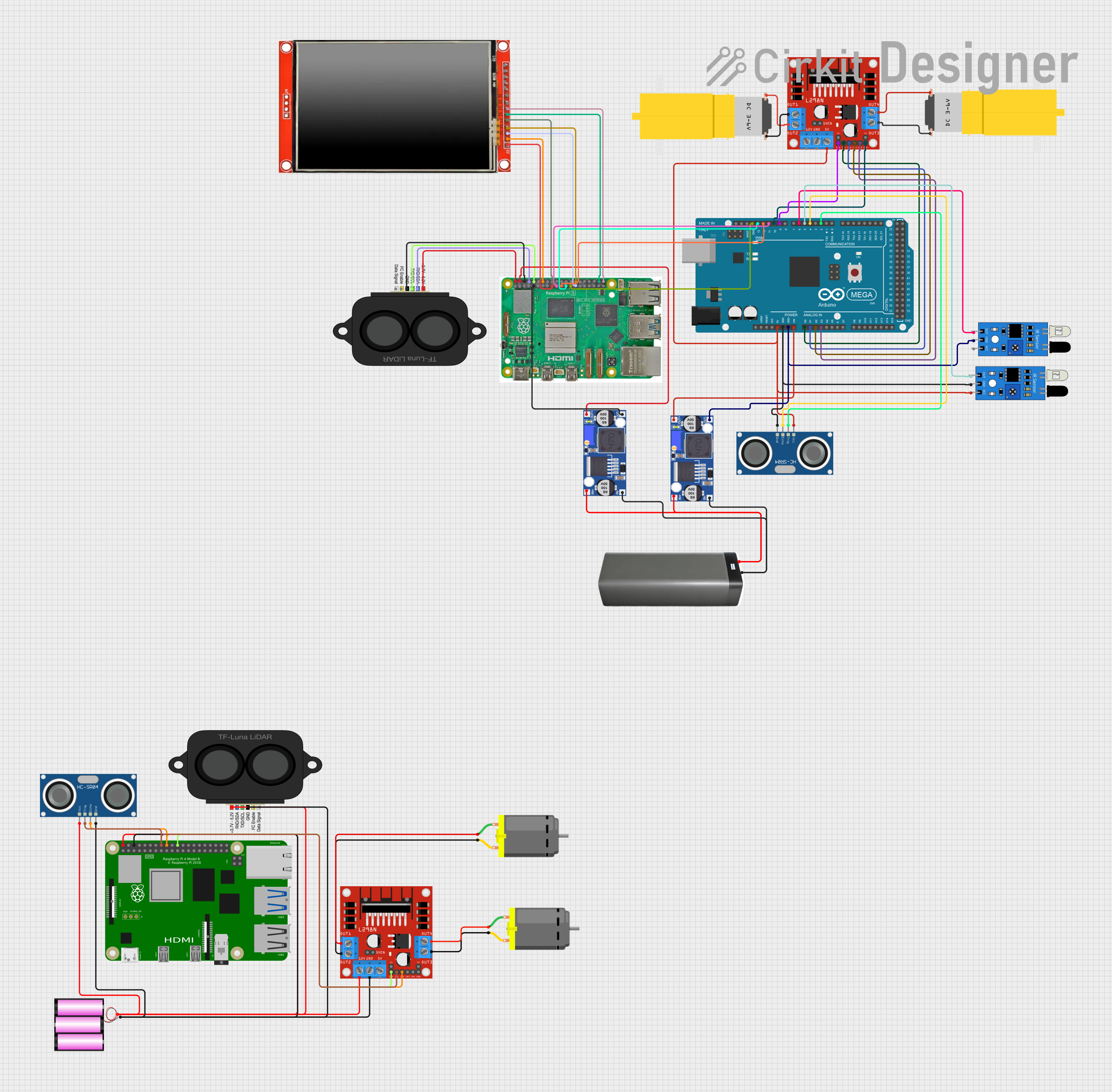
Circuit Documentation
Summary
The circuit in question is a complex system designed to control motors, sense distance, and interface with a user through an LCD screen. It includes a microcontroller (Arduino Mega 2560), motor drivers (L298N), ultrasonic sensors (HC-SR04), IR sensors, buck converters for voltage regulation, battery packs for power supply, a TFT LCD screen (ILI9488 HD), LIDAR modules (TF LUNA LIDAR), DC motors, and Raspberry Pi computers for advanced processing and control.
Component List
Microcontroller
- Arduino Mega 2560: A microcontroller board based on the ATmega2560, with a wide range of input/output options.
Motor Drivers
- L298N DC Motor Driver: A high-power motor driver capable of driving up to 4 DC motors or 2 stepper motors.
Sensors
- HC-SR04 Ultrasonic Sensor: A sensor for measuring distance via ultrasonic sound waves.
- IR Sensor: An infrared sensor for detecting proximity or receiving IR signals.
Power Management
- Buck Converter: A DC-DC converter that steps down voltage from a higher level to a lower level.
- Battery Pack: A power source for the circuit.
- 12V Battery: A 12-volt battery providing power to certain components.
Display
- LCD TFT Screen ILI9488 HD: A high-definition TFT LCD screen for user interface.
Motors
- Motor Amarillo Motorreductor Hobby: A yellow DC gear motor for driving mechanical loads.
Computing Modules
- Raspberry Pi 5: A powerful single-board computer with GPIO capabilities.
- Raspberry Pi 4B: A previous version of the Raspberry Pi single-board computer.
Distance Measurement
- TF LUNA LIDAR: A compact LIDAR sensor for accurate distance measurements.
Actuators
- DC Motor: A simple DC motor for rotational motion.
Wiring Details
Arduino Mega 2560
- 5V: Connected to the 5V power supply from the L298N motor driver and IR sensor.
- GND: Common ground with the IR sensor, HC-SR04, and buck converters.
- VIN: Receives voltage from the buck converter (OUT+).
- A0 - A3: Control signals to the L298N motor driver (IN1 - IN4).
- D2, D4 - D6, D9, D10: Connected to the HC-SR04 sensor (TRIG, ECHO) and IR sensors (out), and enable pins on the L298N motor driver (ENA, ENB).
L298N DC Motor Driver
- 5V: Power supply to the Arduino Mega 2560.
- GND: Common ground with the Arduino Mega 2560.
- IN1 - IN4: Control inputs from the Arduino Mega 2560 (A0 - A3).
- ENA, ENB: Enable pins controlled by the Arduino Mega 2560 (D9, D10).
- OUT1 - OUT4: Outputs to the motors.
HC-SR04 Ultrasonic Sensor
- VCC: Power supply from the 12V battery.
- GND: Common ground with the Arduino Mega 2560.
- TRIG: Trigger pin connected to the Arduino Mega 2560 (D2).
- ECHO: Echo pin connected to the Arduino Mega 2560 (D4).
IR Sensor
- VCC: Power supply from the 5V output of the L298N motor driver.
- GND: Common ground with the Arduino Mega 2560.
- Out: Output signal connected to the Arduino Mega 2560 (D5, D6).
Buck Converter
- IN+, IN-: Input from the battery pack.
- OUT+, OUT-: Output to the Arduino Mega 2560 (VIN, GND) and Raspberry Pi 5 (5V, GND).
Battery Pack
- +, -: Provides power to the buck converters.
Raspberry Pi 5
- GPIO 10, 9, 11: Connected to the Arduino Mega 2560 (D11 - D13).
- GND: Common ground with the Arduino Mega 2560.
- 5V: Power supply from the buck converter.
- GPIO 14, 15: Connected to the TF LUNA LIDAR (RXD/SDA, TXD/SCL).
- GPIO 24, 1, 20, 21, 0: Connected to the LCD TFT screen (D/C, RST, SDI(MOSI), SCK, CS).
- 3.3v: Power supply to the LCD TFT screen.
Raspberry Pi 4B
- 5V, GND: Power supply from the 12V battery.
- GPIO23, 24, 25: Connected to the HC-SR04 sensor (TRIG, ECHO) and L298N motor driver (ENA).
TF LUNA LIDAR
- Power: Power supply from the Raspberry Pi 5 (5V).
- GND: Common ground with the Raspberry Pi 5.
- RXD/SDA, TXD/SCL: Data lines connected to the Raspberry Pi 5 (GPIO 14, 15).
LCD TFT Screen ILI9488 HD
- GND, VCC (3.3~5V), D/C, RST, SDI(MOSI), SCK, CS: Connected to the Raspberry Pi 5 (GND, 3.3v, GPIO 24, 1, 20, 21, 0).
Motors
- Motor Amarillo Motorreductor Hobby: Connected to the L298N motor driver (OUT1, OUT2, OUT3, OUT4).
- DC Motor: Connected to the L298N motor driver (OUT1, OUT2, OUT3, OUT4).
Documented Code
Arduino Mega 2560 Code (sketch.ino)
void setup() {
  // put your setup code here, to run once:

}

void loop() {
  // put your main code here, to run repeatedly:

}
Additional Notes
- The provided code for the Arduino Mega 2560 is a template with empty setup and loop functions. Actual implementation code is required for the circuit to perform its intended functions.
- The Raspberry Pi code is not provided and should be developed according to the specific requirements of the application.
- The connections between the Raspberry Pi and other components suggest the use of SPI and GPIO for interfacing with the LCD screen and LIDAR sensor, respectively.