Arduino Mega 2560 Controlled Linear Actuator and Peristaltic Pump System with NeoPixel Feedback
Circuit Documentation
Summary
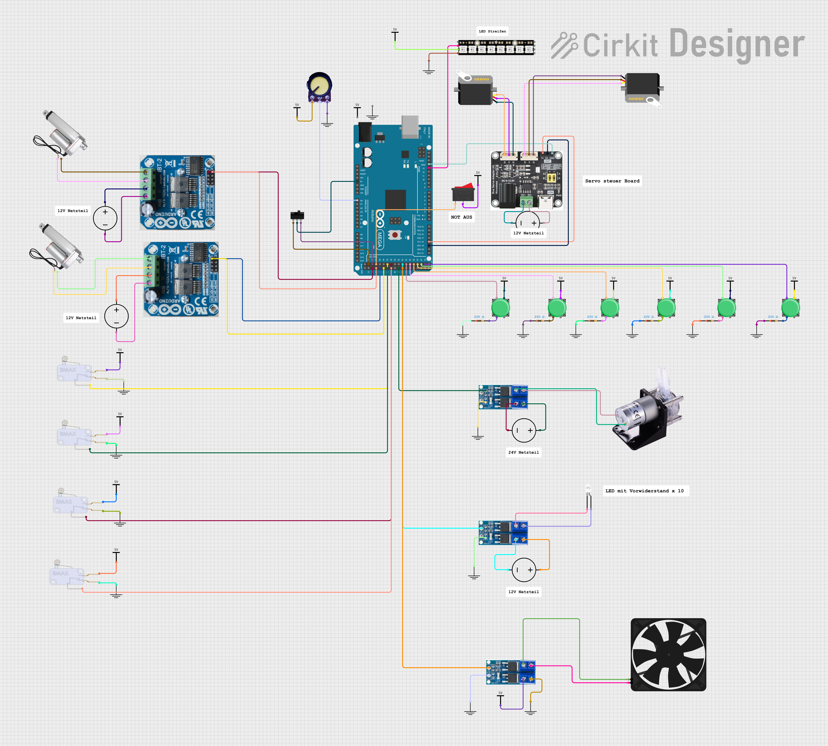
This circuit is designed to control various components including linear actuators, a servo, a peristaltic pump, and an Adafruit NeoPixel Stick using an Arduino Mega 2560 microcontroller. The circuit includes motor drivers for the actuators, power MOSFETs for controlling power to the pump and an LED, and various switches and endstops for user input and limit detection. The Arduino Mega 2560 is the central processing unit that interfaces with all the components to control their behavior based on the programmed logic.
Component List
- Linear Actuators: Used for precision movement control in applications such as robotics or automation.
- Arduino Mega 2560: A microcontroller board based on the ATmega2560, with numerous digital and analog I/O pins.
- Servo: A rotary actuator that allows for precise control of angular position.
- Peristaltic Pump: A type of positive displacement pump used for pumping various fluids.
- Power MOSFETs: Electronic devices used for switching or amplifying electronic signals in the circuit.
- Pushbuttons: Simple switches to provide user input to the microcontroller.
- IBT-2 H-Bridge Motor Drivers: Electronic devices that allow for bidirectional control of motors.
- DC Power Sources: Provide the necessary power to the circuit components.
- Resistors: Passive electrical components that provide resistance in the circuit, used for current limiting or voltage division.
- GND (Ground): Reference point in an electrical circuit from which voltages are measured.
- Vcc: Positive supply voltage terminal.
- Serial Bus Servo: A servo that can be controlled via serial communication.
- Adafruit NeoPixel Stick: An LED strip with individually addressable RGB LEDs.
- LED (white): A two-pin light-emitting diode.
- Potentiometer: A three-terminal resistor with a sliding contact that forms an adjustable voltage divider.
- Toggle Switch: A switch that can maintain its state either on or off.
- Rocker Switch: A button for switching power supply by rocking the switch back and forth.
- Endstop: A switch used to detect the presence or absence of an object or to detect the end of travel of an object.
- Fan: An electric device that creates airflow.
Wiring Details
Linear Actuators
- Connected to the IBT-2 H-Bridge Motor Drivers for control.
Arduino Mega 2560
- Connected to various components for control and monitoring, including the potentiometer (A0), Serial Bus Servo (RX1, TX1), Adafruit NeoPixel Stick (D13 PWM), and several pushbuttons and endstops on various digital pins.
Servo
- Controlled by the Serial Bus Servo for pulse width modulation.
Peristaltic Pump
- Powered through a Power MOSFET for on/off control.
Power MOSFETs
- Used to switch power to the Peristaltic Pump and the white LED.
Pushbuttons
- Connected to the Arduino Mega 2560 with pull-up resistors for user input.
IBT-2 H-Bridge Motor Drivers
- Drive the Linear Actuators and are controlled by the Arduino Mega 2560.
DC Power Sources
- Provide power to the Motor Drivers, Power MOSFETs, and the Serial Bus Servo.
Resistors
- Used as pull-up resistors for the pushbuttons.
Serial Bus Servo
- Controls the Servo and is powered by a DC Power Source.
Adafruit NeoPixel Stick
- Controlled by the Arduino Mega 2560 and powered by a Vcc source.
LED (white)
- Powered through a Power MOSFET.
Potentiometer
- Provides analog input to the Arduino Mega 2560.
Toggle Switch
- Connected to the Arduino Mega 2560 for control logic.
Rocker Switch
- Connected to the Arduino Mega 2560 for control logic.
Endstops
- Connected to the Arduino Mega 2560 for limit detection.
Fan
- Powered through a Power MOSFET for cooling purposes.
Documented Code
void setup() {
  // put your setup code here, to run once:

}

void loop() {
  // put your main code here, to run repeatedly:

}
The provided code is a template for the Arduino Mega 2560 with empty setup() and loop() functions. The setup() function is intended for initialization code that runs once at startup, and the loop() function contains the main logic that runs continuously. Additional code is required to control the connected components based on the circuit's design.