
ESP32C3 and SIM800L Powered Smart Energy Monitor with OLED Display and Wi-Fi Connectivity
View and Edit Project In Cirkit Designer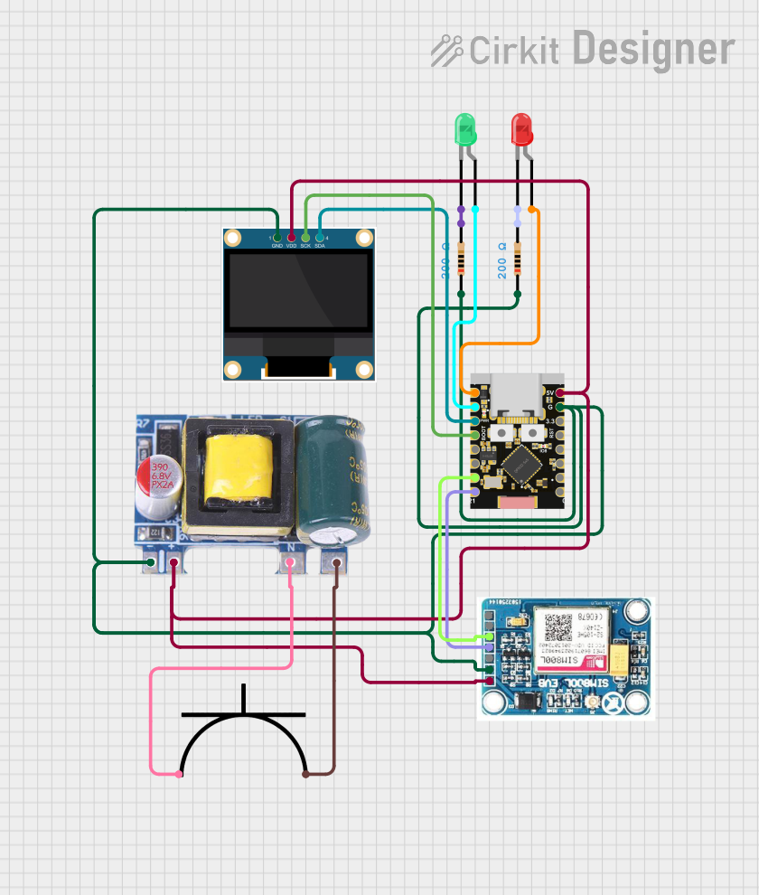
Circuit Documentation
Summary
This circuit is designed to monitor power usage from various slave devices and display the total wattage on a 0.96" OLED display. The circuit includes an ESP32C3 microcontroller, a SIM800L GSM module for SMS communication, and a Mini AC-DC module for power conversion. The ESP32C3 collects data from slave devices via WiFi and SMS, processes the data, and displays the total wattage on the OLED display.
Component List
0.96" OLED
- Pins: GND, VDD, SCK, SDA
- Description: OLED display for showing total wattage.
- Purpose: Display total wattage collected from slave devices.
Mini AC-DC 110V-230V to 5V 700mA Module
- Pins: GND, 5v, Neutral, Life
- Description: AC-DC converter module.
- Purpose: Convert AC power to 5V DC for powering the circuit.
SIM 800L V2.0 GSM
- Pins: SIM_TXD, VDD, SIM.RXD, 5V/4V, GND, RST
- Description: GSM module for SMS communication.
- Purpose: Send and receive SMS for data collection.
ESP32C3 Supermini
- Pins: GPIO05, GPIO06, GPIO07, GPIO08, GPIO09, GPIO10, GPIO20, GPIO21, GPIO00, GPIO01, GPIO02, GPIO03, GPIO04, 3.3V, GND, +5V
- Description: Microcontroller for data processing and communication.
- Purpose: Collect data from slave devices and display it on the OLED.
AC power plug
- Pins: positive terminal, negative terminal
- Description: AC power plug.
- Purpose: Provide AC power to the circuit.
Resistor (200 Ohms)
- Pins: pin1, pin2
- Description: Resistor.
- Purpose: Current limiting for LEDs.
LED: Two Pin (red)
- Pins: cathode, anode
- Description: Red LED.
- Purpose: Visual indicator.
LED: Two Pin (green)
- Pins: cathode, anode
- Description: Green LED.
- Purpose: Visual indicator.
Wiring Details
0.96" OLED
- GND: Connected to GND of ESP32C3, SIM 800L, Mini AC-DC module, and Resistors.
- VDD: Connected to 5V of ESP32C3, SIM 800L, and Mini AC-DC module.
- SCK: Connected to GPIO08 of ESP32C3.
- SDA: Connected to GPIO07 of ESP32C3.
Mini AC-DC 110V-230V to 5V 700mA Module
- GND: Connected to GND of ESP32C3, SIM 800L, OLED, and Resistors.
- 5v: Connected to VDD of ESP32C3, SIM 800L, and OLED.
- Neutral: Connected to negative terminal of AC power plug.
- Life: Connected to positive terminal of AC power plug.
SIM 800L V2.0 GSM
- SIM_TXD: Connected to GPIO21 of ESP32C3.
- VDD: Connected to 5V of ESP32C3, Mini AC-DC module, and OLED.
- SIM.RXD: Connected to GPIO20 of ESP32C3.
- 5V/4V: Connected to 5V of ESP32C3, Mini AC-DC module, and OLED.
- GND: Connected to GND of ESP32C3, Mini AC-DC module, OLED, and Resistors.
- RST: Not connected.
ESP32C3 Supermini
- GPIO05: Connected to anode of red LED.
- GPIO06: Connected to anode of green LED.
- GPIO07: Connected to SDA of OLED.
- GPIO08: Connected to SCK of OLED.
- GPIO20: Connected to SIM.RXD of SIM 800L.
- GPIO21: Connected to SIM_TXD of SIM 800L.
- GND: Connected to GND of SIM 800L, Mini AC-DC module, OLED, and Resistors.
- +5V: Connected to 5V of SIM 800L, Mini AC-DC module, and OLED.
AC power plug
- positive terminal: Connected to Life of Mini AC-DC module.
- negative terminal: Connected to Neutral of Mini AC-DC module.
Resistor (200 Ohms)
- pin1: Connected to GND of ESP32C3, SIM 800L, Mini AC-DC module, and OLED.
- pin2: Connected to cathode of red LED.
Resistor (200 Ohms)
- pin1: Connected to GND of ESP32C3, SIM 800L, Mini AC-DC module, and OLED.
- pin2: Connected to cathode of green LED.
LED: Two Pin (red)
- cathode: Connected to pin2 of Resistor.
- anode: Connected to GPIO05 of ESP32C3.
LED: Two Pin (green)
- cathode: Connected to pin2 of Resistor.
- anode: Connected to GPIO06 of ESP32C3.
Code Documentation
/*
 * This Arduino Sketch is for an ESP32C3 microcontroller that acts as a master
 * device. It collects power usage data from slave devices via WiFi and SMS,
 * and displays the total wattage used on a 0.96" OLED display.
 */
#include <HTTPClient.h>
#include <Wire.h>
#include <Adafruit_GFX.h>
#include <Adafruit_SSD1306.h>
#include <WiFi.h>
#include <SoftwareSerial.h>

#define SCREEN_WIDTH 128
#define SCREEN_HEIGHT 64
#define OLED_RESET    -1
Adafruit_SSD1306 display(SCREEN_WIDTH, SCREEN_HEIGHT, &Wire, OLED_RESET);

const char* ssid = "your_SSID";
const char* password = "your_PASSWORD";

SoftwareSerial sim800l(21, 20); // RX, TX

void setup() {
  // Initialize Serial for debugging
  Serial.begin(115200);

  // Initialize OLED display
  if(!display.begin(SSD1306_SWITCHCAPVCC, 0x3C)) {
    Serial.println(F("SSD1306 allocation failed"));
    for(;;);
  }
  display.display();
  delay(2000);
  display.clearDisplay();

  // Initialize WiFi
  WiFi.begin(ssid, password);
  while (WiFi.status() != WL_CONNECTED) {
    delay(1000);
    Serial.println("Connecting to WiFi...");
  }
  Serial.println("Connected to WiFi");

  // Initialize SIM800L
  sim800l.begin(9600);
  delay(1000);
  sim800l.println("AT");
  delay(100);
  sim800l.println("AT+CMGF=1"); // Set SMS to text mode
  delay(100);
}

void loop() {
  // Placeholder for collecting data from slaves via WiFi and SMS
  float totalWattage = getTotalWattageFromSlaves();

  // Display total wattage on OLED
  display.clearDisplay();
  display.setTextSize(1);
  display.setTextColor(SSD1306_WHITE);
  display.setCursor(0, 0);
  display.print("Total Wattage: ");
  display.print(totalWattage);
  display.println(" W");
  display.display();

  delay(5000); // Update every 5 seconds
}

float getTotalWattageFromSlaves() {
   float totalWattage = 0.0;
  const char* slaveIPs[] = {"192.168.1.101", "192.168.1.102"}; // IP addresses of slave devices
  const int numSlaves = sizeof(slaveIPs) / sizeof(slaveIPs[0]);

  for (int i = 0; i < numSlaves; i++) {
    HTTPClient http;
    String url = String("http://") + slaveIPs[i] + "/getWattage";
    http.begin(url);
    int httpCode = http.GET();

    if (httpCode > 0) {
      String payload = http.getString();
      totalWattage += payload.toFloat();
    } else {
      Serial.print("Error on HTTP request to ");
      Serial.println(slaveIPs[i]);
    }

    http.end();
  }

  return totalWattage;
}
This code initializes the ESP32C3 microcontroller, connects to WiFi, and sets up the SIM800L GSM module for SMS communication. It collects power usage data from slave devices via WiFi and SMS, and displays the total wattage on a 0.96" OLED display. The