Cirkit Designer
Your all-in-one circuit design IDE
Home /
Project Documentation
Arduino Nano RFID Access Control with Servo and Alert Indicators

Circuit Documentation
Summary
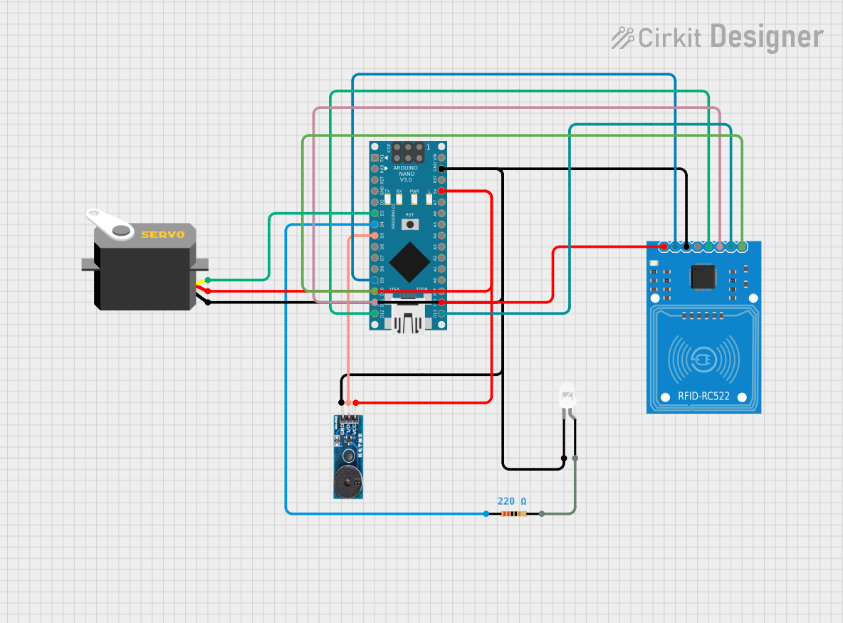
The circuit in question is designed to interface an RFID-RC522 module with an Arduino Nano for RFID reading capabilities. Additionally, the circuit includes a white LED with a current-limiting resistor, a buzzer module for audio feedback, and a servo motor for physical actuation. The Arduino Nano serves as the central controller, managing the RFID reader, driving the LED and buzzer, and controlling the servo based on the program logic defined in the embedded code.
Component List
RFID-RC522
- Description: An RFID reader/writer module for contactless communication at 13.56MHz.
- Pins: SDA, SCK, MOSI, MISO, IRQ, GND, RST, 3.3V
LED: Two Pin (white)
- Description: A white light-emitting diode for visual indication.
- Pins: cathode, anode
Resistor
- Description: A passive two-terminal electrical component that implements electrical resistance as a circuit element.
- Value: 220 Ohms
Buzzer Module
- Description: An audio signaling device, which may be mechanical, electromechanical, or piezoelectric.
- Pins: GND, I/O, VCC
Arduino Nano
- Description: A small, complete, and breadboard-friendly board based on the ATmega328 (Arduino Nano 3.x).
- Pins: D1/TX, D0/RX, RESET, GND, D2, D3, D4, D5, D6, D7, D8, D9, D10, D11/MOSI, D12/MISO, VIN, 5V, A7, A6, A5, A4, A3, A2, A1, A0, AREF, 3V3, D13/SCK
Servo
- Description: A rotary actuator or linear actuator that allows for precise control of angular or linear position, velocity, and acceleration.
- Pins: gnd, vcc, pulse
Wiring Details
RFID-RC522
- SDA connected to Arduino Nano D10
- SCK connected to Arduino Nano D13/SCK
- MOSI connected to Arduino Nano D11/MOSI
- MISO connected to Arduino Nano D12/MISO
- IRQ not connected
- GND connected to common ground
- RST connected to Arduino Nano D9
- 3.3V connected to Arduino Nano 3V3
LED: Two Pin (white)
- cathode connected to common ground
- anode connected to one end of the Resistor
Resistor
- pin1 connected to Arduino Nano D4
- pin2 connected to LED anode
Buzzer Module
- GND connected to common ground
- I/O connected to Arduino Nano D5
- VCC connected to Arduino Nano 5V
Arduino Nano
- GND connected to common ground
- 3V3 connected to RFID-RC522 3.3V
- D3 connected to Servo pulse
- D4 connected to Resistor pin1
- D5 connected to Buzzer Module I/O
- D9 connected to RFID-RC522 RST
- D10 connected to RFID-RC522 SDA
- D11/MOSI connected to RFID-RC522 MOSI
- D12/MISO connected to RFID-RC522 MISO
- D13/SCK connected to RFID-RC522 SCK
- 5V connected to Buzzer Module VCC and Servo vcc
Servo
- gnd connected to common ground
- vcc connected to Arduino Nano 5V
- pulse connected to Arduino Nano D3
Documented Code
Arduino Nano Code (sketch.ino)
void setup() {
  // put your setup code here, to run once:

}

void loop() {
  // put your main code here, to run repeatedly:

}
Note: The provided code is a template and does not contain any functional logic. It needs to be populated with the setup and loop functions to control the RFID-RC522, LED, Buzzer, and Servo based on the requirements of the application.