
Arduino Mega 2560-Based Smart Lock System with Servo Control and GSM Connectivity
View and Edit Project In Cirkit Designer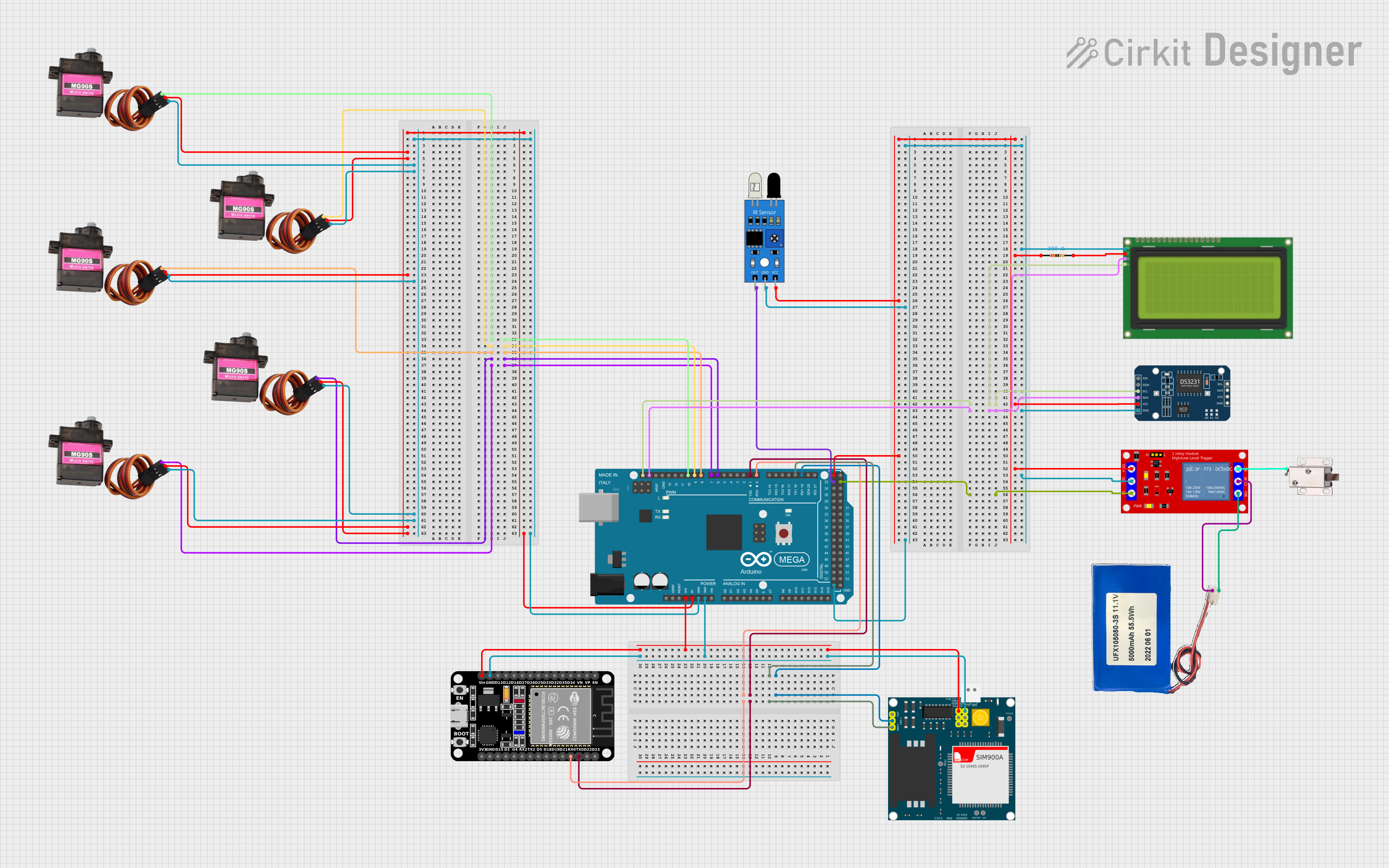
Circuit Documentation
Summary
This circuit involves an Arduino Mega 2560 microcontroller interfacing with various components including multiple MG90S servos, an LCD display, a DS3231 RTC module, a 1 Channel 5V Relay Module, a SIM900A GSM module, an ESP32, an IR sensor, a 12V solenoid lock, and a Li-ion battery. The circuit is designed to control servos, display information on an LCD, manage real-time clock data, control a relay, communicate via GSM, and sense infrared signals.
Component List
Resistor
- Description: A 220 Ohm resistor.
- Pins: pin1, pin2
- Properties:
- Resistance: 220 Ohms
Arduino Mega 2560
- Description: A microcontroller board based on the ATmega2560.
- Pins: IOREF, RESET, 3V3, 5V, GND, VIN, A0-A15, D0-D53, AREF, SDA, SCL
- Properties: None
MG90S Servo Motors
- Description: Micro servo motors.
- Pins: SIG, VCC, GND
- Properties: None
Lcd 20x4 i2c
- Description: 20x4 character LCD with I2C interface.
- Pins: GND, 5v, SCA, SCL
- Properties: None
DS3231 RTC
- Description: Real-time clock module.
- Pins: 32K, SQW, SCL, SDA, VCC, GND
- Properties: None
1 Channel 5V Relay Module
- Description: Relay module for switching high voltage devices.
- Pins: VCC+, VCC- (GND), IN, N.O., COM, N.C.
- Properties: None
SIM900A
- Description: GSM module for communication.
- Pins: GND, DB9-3 (RXD), DB9-2 (TXD), 5V, 3VR, 5VR, 3VT, 5VT, VCC, Ring, RESTART, RESET, STATUS
- Properties: None
ESP32 (30 pin)
- Description: Wi-Fi and Bluetooth microcontroller.
- Pins: EN, VP, VN, D34, D35, D32, D33, D25, D26, D27, D14, D12, D13, GND, Vin, D23, D22, TX0, RX0, D21, D19, D18, D5, TX2, RX2, D4, D2, D15, 3V3
- Properties: None
IR Sensor
- Description: Infrared sensor for object detection.
- Pins: out, gnd, vcc
- Properties: None
12V Solenoid Lock
- Description: Electromagnetic lock.
- Pins: VCC, GND
- Properties: None
Li-ion 5000mAh Battery
- Description: Rechargeable battery.
- Pins: 11.1V, GND
- Properties: None
Wiring Details
Resistor
- pin1: Connected to VCC of IR sensor, VCC of DS3231 RTC, 5V of Arduino Mega 2560, VCC+ of 1 Channel 5V Relay Module
- pin2: Connected to 5v of Lcd 20x4 i2c
Arduino Mega 2560
- D10 PWM: Connected to SIG of MG90S
- D9 PWM: Connected to SIG of MG90S
- D8 PWM: Connected to SIG of MG90S
- D6 PWM: Connected to SIG of MG90S
- D7 PWM: Connected to SIG of MG90S
- SCL: Connected to SCL of Lcd 20x4 i2c, SCL of DS3231 RTC
- SDA: Connected to SCA of Lcd 20x4 i2c, SDA of DS3231 RTC
- D23: Connected to IN of 1 Channel 5V Relay Module
- D19/RX1: Connected to DB9-3 (RXD) of SIM900A
- D18/TX1: Connected to DB9-2 (TXD) of SIM900A
- D1 TX0: Connected to TX0 of ESP32
- D0 RX0: Connected to RX0 of ESP32
- 5V: Connected to VCC of MG90S, VCC of Lcd 20x4 i2c, VCC of DS3231 RTC, VCC+ of 1 Channel 5V Relay Module
- GND: Connected to GND of MG90S, GND of Lcd 20x4 i2c, GND of IR sensor, GND of DS3231 RTC, VCC- (GND) of 1 Channel 5V Relay Module, GND of SIM900A, GND of ESP32
- 3V3: Connected to VCC of SIM900A, Vin of ESP32
- D22: Connected to out of IR sensor
MG90S Servo Motors
- SIG: Connected to D10 PWM, D9 PWM, D8 PWM, D6 PWM, D7 PWM of Arduino Mega 2560
- VCC: Connected to 5V of Arduino Mega 2560
- GND: Connected to GND of Arduino Mega 2560
Lcd 20x4 i2c
- SCL: Connected to SCL of Arduino Mega 2560, SCL of DS3231 RTC
- SCA: Connected to SDA of Arduino Mega 2560, SDA of DS3231 RTC
- GND: Connected to GND of Arduino Mega 2560
- 5v: Connected to pin2 of Resistor
DS3231 RTC
- SCL: Connected to SCL of Arduino Mega 2560, SCL of Lcd 20x4 i2c
- SDA: Connected to SDA of Arduino Mega 2560, SCA of Lcd 20x4 i2c
- VCC: Connected to pin1 of Resistor
- GND: Connected to GND of Arduino Mega 2560
1 Channel 5V Relay Module
- IN: Connected to D23 of Arduino Mega 2560
- VCC+: Connected to pin1 of Resistor
- VCC- (GND): Connected to GND of Arduino Mega 2560
- N.O.: Connected to GND of Li-ion 5000mAh Battery
- COM: Connected to 11.1V of Li-ion 5000mAh Battery
- N.C.: Connected to VCC of 12V Solenoid Lock
SIM900A
- DB9-3 (RXD): Connected to D19/RX1 of Arduino Mega 2560
- DB9-2 (TXD): Connected to D18/TX1 of Arduino Mega 2560
- VCC: Connected to 3V3 of Arduino Mega 2560
- GND: Connected to GND of Arduino Mega 2560
ESP32 (30 pin)
- TX0: Connected to D1 TX0 of Arduino Mega 2560
- RX0: Connected to D0 RX0 of Arduino Mega 2560
- Vin: Connected to 3V3 of Arduino Mega 2560
- GND: Connected to GND of Arduino Mega 2560
IR Sensor
- out: Connected to D22 of Arduino Mega 2560
- gnd: Connected to GND of Arduino Mega 2560
- vcc: Connected to pin1 of Resistor
12V Solenoid Lock
- VCC: Connected to N.C. of 1 Channel 5V Relay Module
- GND: No connection specified
Li-ion 5000mAh Battery
- 11.1V: Connected to COM of 1 Channel 5V Relay Module
- GND: Connected to N.O. of 1 Channel 5V Relay Module
Documented Code
Arduino Mega 2560 Code
void setup() {
  // put your setup code here, to run once:

}

void loop() {
  // put your main code here, to run repeatedly:

}
This code is a basic template for the Arduino Mega 2560. The setup() function is used to initialize any settings or configurations, and the loop() function contains the main code that runs repeatedly.